Hi.
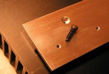
For Kristian's Aleph 2,3,4,5 series PCBs, here is an idea or suggestion of haw can you
place the 240s or 244s on effective way and easy placement and replacement.
I am just looking for the big wide sil-pad or mica insulator that I can use for that aluminum profile
so that I can isolate the heatsink from the profile.
In this way Transistors are mounted directly on the aluminum what further improves heat transfer.
Any comments?
Attachments

In one way it's good in another it's not.😉 Where did you get those bars?
If you got them for free and got bigger than usual heat sinks, it's all right.
Otherwise there are better ways to mount those FETs. But you know my POV anyway.😉
If you got them for free and got bigger than usual heat sinks, it's all right.
Otherwise there are better ways to mount those FETs. But you know my POV anyway.😉
Hi Peter.
My friend did it for me 😉 and heatsinks are you know, kind of big, 4 of them for 2 monoblocks of Aleph 4. Here they are. I've got new camera and still fighting with size of images
Those bars are actually big, they should do the job.
Here it is.
My friend did it for me 😉 and heatsinks are you know, kind of big, 4 of them for 2 monoblocks of Aleph 4. Here they are. I've got new camera and still fighting with size of images
Those bars are actually big, they should do the job.
Here it is.
Attachments

Hello Trigon,
That's a good idea - the larger surface area between the mounting bar and heatsink will give a lower thermal impedance (case to HS) than isolating the MOSFETs individually. I did something similar on my Hiraga Classe A.
You can buy large sheets of insulating material which the user then cuts to the size they need. For example, Farnell item number 279900 is a 300mm x 300mm sheet with a quoted thermal resistance of 0.23'C/W (I think this is per cm^2 of area, although this isn't specified). Price is just under £7 - about $10.
Nice one,
David
Actually I was thinking not to have MOSFETs individually isolated as they have drains short-connected anyway (Aleph 4). What I was referring to is to isolate the whole bar in which case transistor dissipate directly on the bar which increase the silicone cooling plate so that junction temperature is lower. Thanks for the info.
🙂 Trigon
🙂 Trigon
I don't know if that is what Farnell stocks but Alutronic sheets.
http://www.alutronic.de/e/aluDB.php?UGruppe=Silicone+wafers,+glass+fiber+reinforced
You don't think it is a bit risky to mount them without insulation? The risk of connecting any of the Drains to the mounting bar is quite high meaning that the whole bar is your Drains. Oviously I know you are using silpads to transfer the heat from the bar to the sink/chassis but they will most likely be electrically connected through the screws which would need insulation as well which I can not see in your pictures. I suspect this would make it hard to use the required torque to attach it to the sink unless using lots of screws.
Otherwise it looks really good. Should be a nice amp..
/UrSv
Trigon,
I think you misread my post - I'm agreeing with you! Insulating the bar from the main heatsink would give better heat transfer than isolating the MOSFETs individually with the bar connected directly to the HS.
I also missed the bolt issue. Plastic M4-sized bushes are probably available though.
Nice one,
David.
daatkins
Uppsss, I guess you are right, sorry
UrSv ; daatkins
 As I still have not drilled the holles on the heatsink side I think that I should replaced the screws with M3 and use Plastic M3-sized bushes , if I don't get M4s. Or maybe I can make some M4 bushes of some kind of hard insulating material, like kind of fibreglass or soo + some nice tubing. (hand made bushes 😎 )
Thanks guys for the tips
😉 Trigon
I think you misread my post - I'm agreeing with you! Insulating the bar from the main heatsink would give better heat transfer than isolating the MOSFETs individually with the bar connected directly to the HS
Uppsss, I guess you are right, sorry
UrSv ; daatkins
I also missed the bolt issue. Plastic M4-sized bushes are probably available though.
As I still have not drilled the holles on the heatsink side I think that I should replaced the screws with M3 and use Plastic M3-sized bushes , if I don't get M4s. Or maybe I can make some M4 bushes of some kind of hard insulating material, like kind of fibreglass or soo + some nice tubing. (hand made bushes 😎 )Thanks guys for the tips
😉 Trigon
Connection through the screws.
UrSv: If you have a look on the bottom side of your IRFP240 (which I for sure know you have at home), you'll see that there is little chance for connecting the screws to that metal piece on the "back side".
The insulating tubes are mainly for TO3.
Best,
//magnus
UrSv: If you have a look on the bottom side of your IRFP240 (which I for sure know you have at home), you'll see that there is little chance for connecting the screws to that metal piece on the "back side".
The insulating tubes are mainly for TO3.
Best,
//magnus
Swede, yep.
My concern was mainly that the bars would be connected to the heatsink/chassis by the screw which means that any Drain that comes in contact with the mounting bar will be connected to the chassis. Any metal flake or other thing could do that.
You know I am picky...you should see my "finfilters".
/UrSv
You can forget about using plastic screws to connect the bars to the sinks. Those plastic screws are not strong enough (M3 or M4 are definitely a no-no😉 ), unles you go for a larger size or use some other, stronger material. It would be even better if the bar was done out of copper. I've seen large insulating sheets in Digi-Key catalog, but they were quite expensive.
Why don't you just mount your FETs directly to the heatsiks and forget about all that troube?😉
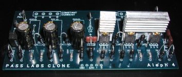
Looks like Caddock MK 132 resistors would be perfect for using with that board. I don't like resistors placed vertically for no apparent reason.🙂
Ampman, the heat sinks come from Mississauga, from R-Theta.
Why don't you just mount your FETs directly to the heatsiks and forget about all that troube?😉
Looks like Caddock MK 132 resistors would be perfect for using with that board. I don't like resistors placed vertically for no apparent reason.🙂
Ampman, the heat sinks come from Mississauga, from R-Theta.
Hello trigon,
I agree with Peter, the plastic screws would not be very good.
You can find silicone isolators in sheets 300 x 300 mm
(11,8 x 11,8 in) at http://www.rs-components.com ,
stock no. 403-279.
Your enclosed alu-profile would work ok.
You must note that some, not all, heatsinks are not perfectly
strait on the base, especially if they are very wide, so it would be a better idea to use silicone rubber isolators, instead mica types,
when you want to joint two longer sides with larger surface area.
With silicone rubber there will be less possibility for the gaps,
than with mica type, and the whole thing would be little more
efficient.
Also, for even better heat transfer, the Cu profile, instead Al,
would be even more efficient.
Best regards,
Kristijan Kljucaric
http://web.vip.hr/pcb-design.vip
Hi.
Peter, would you happen to have any idea for the following problem:
My drill press is not reaching a distance needed for my alu-bars,
so that they can be installed on the center of my heatsinks, it is close
but not sure if it is ok?
I have not talked about plastic M3 or M4 screws that I wonted to use, instead
I was talking about M4 plastic bushes (iso-tips), but it looks to me that UrSv is right, it is to
dangerous to have those bars under the voltage.
But I still think that using three screws instead of six is advantage of using those bars.
Only problem that I am facing now is explained above and by the picture itself.
Not sure if using a Hand Drill I can achieve the good results of drilling three centre holles for those
bars. Got this drill press a 2-3 weeks ago from Canadian tire for $64.00 Canadian.
P.S. Peter I have placed resistors vertically because of the PCB layout where H4 can't fit
so not much choice, but as mentioned before, maybe later I will replaced them with Cadocks.
Thanks for any tip in advance
Trigon
Attachments
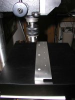
I don't know if you noticed, but there is only one hole to be drilled by hand: the one in a center. To do it straight, you might make yourself a drill guide, like I show it here: http://www.diyvideo.com/forums/showthread.php?s=&threadid=3981&perpage=15&pagenumber=8
- Status
- Not open for further replies.
- Home
- Amplifiers
- Pass Labs
- Kristian's Aleph 2,3,4,5 series PCBs