It is not correct. Be carefull, this was my first try of "the Stellema amplifier". Look into the thread and read it to the end.I have found this.
Who knows if it is correct?
The end is the starting point of my krill-idea.
There is at the moment no layout or pcb.
HBt.

The zipped files contains here is for KiCAD, this was shared by one forum member named m0rten. You may want to pm him for clarifications.
Attachments
Last edited:
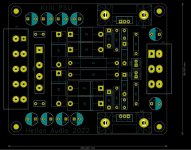
A few years ago I made several PCBs for the Krill amp.
One Krill driver board - needs external OPS.
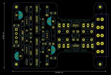
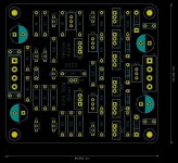
One Krill OPS - 0dB buffer only. Includes 2 pairs ouput transistors with provision for more on external board/heatsink.
One Krill PSU
If anyone wants the KiCAD project folder, it is here as well.
😎 morten
One Krill driver board - needs external OPS.
One Krill OPS - 0dB buffer only. Includes 2 pairs ouput transistors with provision for more on external board/heatsink.
One Krill PSU
If anyone wants the KiCAD project folder, it is here as well.
😎 morten
Attachments
-
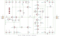 Krill_50W_input_driver_board_skjema_mg.JPG172.3 KB · Views: 64
 -
 Krill_50W_output_board_mg.JPG197.6 KB · Views: 65
 -
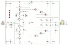 Krill_50W_output_board_skjema_mg.JPG152.1 KB · Views: 58
 -
 Krill_50W_PCB_mg.JPG153.6 KB · Views: 59
 -
 Krill_50W_PSU_layout_mg.JPG188.7 KB · Views: 47
 -
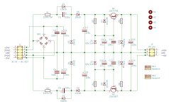 Krill_50W_PSU_skjema_mg.JPG125 KB · Views: 61