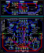
I also have the impression that the traces are a bit to close to the groundplane.
Al, any chance for output boards?
Al, any chance for output boards?
That's just the dimension line, the DRC will keep the GP 20mils away from other traces.
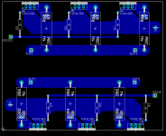
If enough people ask for an output board, I will make one, but after thought, I suspect most people's heatsink mounting arrangements will make it impossible to do a generic one
If enough people ask for an output board, I will make one, but after thought, I suspect most people's heatsink mounting arrangements will make it impossible to do a generic one
Upupa Epops said:Aaron, are you building welding machine ? In class A is it not neccessary 😀 .
Oh, yes it is !!!

Member
Joined 2002
Upupa Epops said:Aaron, are you building welding machine ? In class A is it not neccessary 😀 .
Always!!! Definately needed!
jacco vermeulen said:
Oh, yes it is !!!
Indeed the man is right!!!
It sounds very nice now, it's hard to pick the difference immediately from my Peavey amp... But it's definately different the more i listen the more it's different!!
I'm happy with 4 ohm load, can't see me needing 2 ohm, but i guess you never know! 8 ohm would be very very safe as a load, 4 ohm seems to work very well, but 35 deg above ambient is

Aaron
Hi Pinkmouse,
Just a suggestion;-
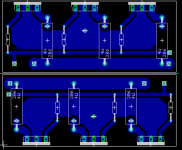
try spacing the outputs a little further apart and then squeeze in another one into each gap to give a choice of 3pairs (well spaced out) or 5pairs (close coupled) or even 2 output boards for 6/10pairs. Whole range of options to suit most tastes.
Keep the PCB same size or even slightly smaller to save on costs.
I'm going to try hard wiring & see how neat/untidy it turns out, might be back to buy output boards if it's a dog's dinner.
Will the driver board sit underneath the output board or could it be integrated into it?
Just a suggestion;-
try spacing the outputs a little further apart and then squeeze in another one into each gap to give a choice of 3pairs (well spaced out) or 5pairs (close coupled) or even 2 output boards for 6/10pairs. Whole range of options to suit most tastes.
Keep the PCB same size or even slightly smaller to save on costs.
I'm going to try hard wiring & see how neat/untidy it turns out, might be back to buy output boards if it's a dog's dinner.
Will the driver board sit underneath the output board or could it be integrated into it?
Hi Andrew
As I've had the experience of my hardwired prototype up and running, I would be very loathe to put more output devices on that board. These amps kick out a lot of heat, and to help the heatsinking as much as possible, I think it's best to keep the transistors well spaced. If you are going for a monster amp, then the cost of another board or two will be minor compared the the cost of the outputs, heatsinking and caps required.
As for the pcb, I'll keep it separate from the main board, as I suspect many will be hardwiring the outputs, and thus won't need it. It is the same width as the other pcbs, and I'm sure when I get to tweaking the height will shrink a little. I see no reason at all why it couldn't be mounted underneath the main pcb, if you so require.
Hi pinkmouse,
sorry I didn't explain carefully enough.
The driver board not the main amplifying board should be beside or below the outputs to allow thermal coupling/feedback to control Iq. Am I right?
Your logic re heat and spacing accepted. Just keep to 3 on a board.
sorry I didn't explain carefully enough.
The driver board not the main amplifying board should be beside or below the outputs to allow thermal coupling/feedback to control Iq. Am I right?
Your logic re heat and spacing accepted. Just keep to 3 on a board.
Yes, but as this is a Class A amp it's not so critical, a separate beefy heatsink will do. The concensus to put them on the main board only came about because they run a tad on the hot side.😉
Oh, and the pcb above is wrong. For some reason known only to itself ,Eagle seems to have substituted T0220 packages for the T0247s I specified...
Oh, and the pcb above is wrong. For some reason known only to itself ,Eagle seems to have substituted T0220 packages for the T0247s I specified...
Hi,
completely off topic & hi-jacking to boot.
Is there a WIKI to teach me how to use this Forum properly?
For instance quotes, funny faces, compressing schematics below 100k etc.
completely off topic & hi-jacking to boot.
Is there a WIKI to teach me how to use this Forum properly?
For instance quotes, funny faces, compressing schematics below 100k etc.
- Home
- Amplifiers
- Solid State
- Krell KSA 50 PCB