True! ")
Still need to rebuild mine, but when it was working, I had all earths running back to a star between the two PSU caps, I did think about trying an inductor, but with no observable noise, just never got 'round to it.
If I was doing the design now, 15 years later, I suspect I might be a bit more rigorous in measurements and noise analysis, but then all I had was a 1960's scope, and lots and lots of multimeters !
Symbol Name Description
 Earth Ground Used for zero potential reference and electrical shock protection.
 Chassis Ground Connected to the chassis of the circuit
 Digital / Common Ground
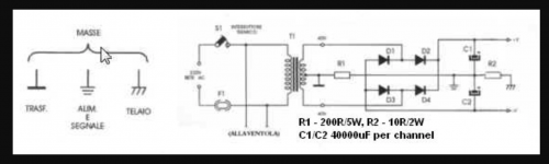
According to the schematic the "earth returns at the output terminate between R1 & R2 of the power supply diagram.
That seems to work for some of the posters replying to you but I have never used the Krell "method " so I use the "old fashioned way " -directly connected via the JLH "way of doing this " ---and its never let me down , but its "horses for courses " if the Krell way works better in a Krell amplifier who am I to argue with that ?---your choice .
That seems to work for some of the posters replying to you but I have never used the Krell "method " so I use the "old fashioned way " -directly connected via the JLH "way of doing this " ---and its never let me down , but its "horses for courses " if the Krell way works better in a Krell amplifier who am I to argue with that ?---your choice .
If it "doesn't work for me " well in that case as your own power supply shows connect the common directly to the mains earth just do that.
If that is no better then the "JLH way" involves ,as I said separating the output earth returns from the input via a 10 ohm resistor but that's a lot more work as it involves ALL the returns .
If that is no better then the "JLH way" involves ,as I said separating the output earth returns from the input via a 10 ohm resistor but that's a lot more work as it involves ALL the returns .
Duncan,
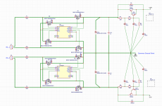
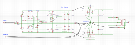
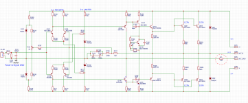
this is how I modified one channel. The second one with LT4320 is very noisy, simple diode bridge seems tp be slightly better. The resistor 200R between centre tap and GND like originally Krell did not work here. 100Hz in speaker output is 200mV.
Any suggestion on this?
this is how I modified one channel. The second one with LT4320 is very noisy, simple diode bridge seems tp be slightly better. The resistor 200R between centre tap and GND like originally Krell did not work here. 100Hz in speaker output is 200mV.
Any suggestion on this?
Attachments
Never had any hum on my 50s as 2 mono blocks.
Quite as a church mouse with perfectly low dc offset as well.
Regards
David
did you make a clone of this?

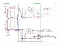
You should draw wiring/grounding of your amp. The HBR is only help if cross channel ground loop happened. Pls see pic as below.
It's easily to understand that there is any common ground in dual mono design. Chassis earth is connected via loop breaker circuit.
It's easily to understand that there is any common ground in dual mono design. Chassis earth is connected via loop breaker circuit.
Attachments
In my post #6 of a JLH design the purpose is not to separate two channels as far as earth returns is concerned but to separate BOTH the INPUT and OUTPUT sections of ONE single amplifier .
This is NOT the same as just separating earth returns between EACH power amplifier , there are design technicalities involved .
Anybody criticising this I hope they have already read John,s reasons for doing this in technical journals.
This is NOT the same as just separating earth returns between EACH power amplifier , there are design technicalities involved .
Anybody criticising this I hope they have already read John,s reasons for doing this in technical journals.
There isn't a "ground 3 " its a printing error .
Ground #1& ground #2 are connected with a 10 ohm resistor which is taken to a star earth exactly in the same place as as the output ground return .
The reason for that is high currents are involved in the output earth return and to reduce cable resistance causing feedback into the amplifier the output earth return is connected by a VERY short length of cable to the star earth --and yes if anybody has read the articles "back resistance " can cause re-injection of output current noise .
To some this may sound OTT but it is based entirely on science --not conjecture or subjectivism.
- Status
- This old topic is closed. If you want to reopen this topic, contact a moderator using the "Report Post" button.
- Home
- Amplifiers
- Solid State
- Krell KSA-50 not quite a clone (Hum Breaking Resistor)