The supply is +50.x/-50.x VDC very possible ., the total loss is within what the forced cooling can cope.., btw the amplifier is running in Class B at maximum output power
187w at 8 ohms with 2.8 amps bias- That must be throwing off a lot of heat!
I measured
62 degree Celsius/143.5 degree Fahrenheit
On the housing of the warmest of the 8 output transistors
Last edited:
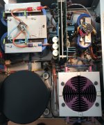
Slow progress in my KMA-100 Refurbishment.
But i did finally bench test the functional amp of the pair
Output just below onset of clipping
187W 8Ohm & 324W 4Ohm
Idle current 2.8A
DC offset 3mV
Excellent. What are your DC rails?
Has to be more. Even with a perfect voltage source, you can't get more than 163w with 50/50 DC rails. Is the 50-0-50 AC? ?
Remember the KMA-100 do have a dedicated Regulated power supply for the driver board, of which the output is +75/-75 VDC
The power supply is a matter fact
+53.5/-53.5 VDC in idle .., the first measured was full power into 8Ohm
+53.5/-53.5 VDC in idle .., the first measured was full power into 8Ohm
Remember the KMA-100 do have a dedicated Regulated power supply for the driver board, of which the output is +75/-75 VDC
Somewhat of topic...
I do have a pair of KMA-100 Mk2's which uses a pair of capacitor technology blue filter-capacitors, instead of the 16 orange 470uF 100V axial Roedersteins which I've seen often with Mk2's.
I presume the ones with this additional regulator add-on board is the latest incarnation of the KMA-100 Mk2?
I have the same regulator setup in my Krell KRS-100 monos which are from 1989. The additional 16 axial Roedersteins are on the underside of the metal plate divider so you can't see them in the picture.
These KRS-100's have Hitachi J56/K170 TO3 MOSFET drivers on top of each of the 6 cooling heatsinks, so one J56 or K176 accompanied with three MJE-15024 or 15025 bipolar outputtransistors.
The regulator supplies regulated DC to the pre-driver stage when I switch the rockerswitch/circuitbreaker on the back, but I wonder if it also powers up the drivers.
When I switch on the circuitbreaker on the back it uses 60 Watts AC when I thereafter switch on the front rockerswitch/circuitbreaker bias is supplied to the outputtransistors and the unit uses approx. 650 Watts.
Not being a technician I'm in doubt what are the differences (apart from the obvious physical dimensions and an extra set of filtercapacitors (the KRS-100 has six Sprague 40,000uF, 90 V and 95 *C filtercapacitors) what are the differences between the KMA-100 Mk2 and KRS-100. The both have a 1200 Watts Avel Lindberg torodial and the same regulator setup.
https://www.diyaudio.com/forums/attachment.php?attachmentid=929317&stc=1&d=1615104950
https://www.diyaudio.com/forums/attachment.php?attachmentid=929319&stc=1&d=1615104950
https://www.diyaudio.com/forums/attachment.php?attachmentid=929318&stc=1&d=1615104950
Attachments
View attachment 736926
View attachment 736927
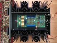
Working on Ksa 100 Mk 2 Clon. Enclosure 35 Kg. Front 10.5 Kg.
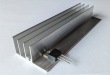
Where did you get the PCB? (And aluminum heatsink bracket for the output transistors?)
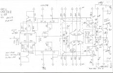
What is the difference between the Mk 2 and Mk 1 circuit?
Very much like this.
DKK 1,212.42 10%OFF | ZEROZONE One pair 40W +40W Class A Power amplifier kit base on KSA100MKII circuit L6-19
ZEROZONE One pair 40W +40W Class A Power amplifier kit base on KSA100MKII circuit L6 19|Amplifier| - AliExpress
DKK 1,212.42 10%OFF | ZEROZONE One pair 40W +40W Class A Power amplifier kit base on KSA100MKII circuit L6-19
ZEROZONE One pair 40W +40W Class A Power amplifier kit base on KSA100MKII circuit L6 19|Amplifier| - AliExpress
Those look like nice boards and heat sink brackets.
I am enjoying my KSA50 Mk I clone and I am looking at a ZERO ZONE KSA50 Mk II board to see if I can hear the difference between the Mk I and Mk II. Over on another forum someone described the difference as follows:
I am enjoying my KSA50 Mk I clone and I am looking at a ZERO ZONE KSA50 Mk II board to see if I can hear the difference between the Mk I and Mk II. Over on another forum someone described the difference as follows:
As far as I can tell from searching for schematics the main difference between the Mk I and Mk II is lower loading on the input stage due to the addition of two additional transistors. (Inside the blue rectangle on the attached image.) If someone more knowledge about Krells can confirm that would be appreciated.The mkii is a cleaner sound. More open. Very fluid upper frequencies. Both mki and 2 deliver solid krell trademark bass.
Attachments

salve alcuni di voi qui a file gerber x realizzare pcb ksa100 schema originale, con bom ecc. ?? grazie


hi.
these are mine.
KSA-100mk2 in mono version.


these are mine.
KSA-100mk2 in mono version.
- Home
- Amplifiers
- Solid State
- Krell KSA 100mkII Clone