PWatts,
I think you forgot one component and I think its because its not shown in the schematic:
the 20pF feedback Silvered Mica capacitor (paralleled to R15 I think you said) I dont know how important this cap is but, it could be beneficially to also have it in the BOM though Krell used it in the KSA 100mk-IIs feedback network.
Regards 😎
Hi,
that 20pF could be critical to stability and/or overshoot when the load is slightly capacitive.
that 20pF could be critical to stability and/or overshoot when the load is slightly capacitive.
I forgot about that cap.. don't think it's really necessary in most cases but rather be safe. I've included it, cannot do harm although it would have to be piggy-backed as I didn't have room to place it.
I just deleted the original spreadsheet by accident so any changes will have to be an addendum
I just deleted the original spreadsheet by accident so any changes will have to be an addendum
Attachments
hi everyone
not sure (noob alert 🙂 ) if we have to confirm our GB payment in this thread, but I have sent payment for 3 boards.
I should add many thanks for everyones efforts on this.
One thing I have yet to see on this thread or elsewhere - and this is for those who are scratch building an amp - is, what values the output resistor and cap are (see here - lower rhs )
Mike
The zobel value of the original was 5R6 in series with 100nF, but the resistor value isn't super-critical as long as it is between approx. 4R7 and 10R.
Note that these should be located as close to the speaker termianals as possible; not at the PCB or transistors etc. Krell tack-soldered them directly onto the connectors.
Note that these should be located as close to the speaker termianals as possible; not at the PCB or transistors etc. Krell tack-soldered them directly onto the connectors.
I sure would be interested in any group buy for heats sinks also, but don't know the appropriate way to calculate what is needed and to compare that to what is offered by the manufacturers. I want to build two monoblocks.Any movement on Heat Sink GB?
Andrew, let me see first if I have any floating around before I break up new boards.....
As far as heatsinks go we were only going be doing a GB for the driver Heat Sink.... not the main sinks. If you or someone else would like to organize a GB for the driver sink that would be a big help!! I'm pretty bogged down at work and someone taking that on would help. The boards are no real big deal even when I'm on the road since I can stuff envelopes at night and go to what ever is the nearest Post Office to mail them.
Mari
Mark A. Gulbrandsen said:Andrew, let me see first if I have any floating around before I break up new boards.....
As far as heatsinks go we were only going be doing a GB for the driver Heat Sink.... not the main sinks. If you or someone else would like to organize a GB for the driver sink that would be a big help!! I'm pretty bogged down at work and someone taking that on would help. The boards are no real big deal even when I'm on the road since I can stuff envelopes at night and go to what ever is the nearest Post Office to mail them.
Mari
Hy Mari!
on your way to post office,you can shoot me with one set of old ones

mebbe I can try to make one nice headphone amp

.......I just can't resist...........
Some people have indicated to me that they cannot find the WIKI... so here is where its at...... I have also added it to my signature so it will be easier to find.
We are at about the 50% mark as far as receiving money for those that have signed up. I will post a list later on of those that I have recenved payment from.
KSA-100 PCB Group Buy
We are at about the 50% mark as far as receiving money for those that have signed up. I will post a list later on of those that I have recenved payment from.
KSA-100 PCB Group Buy
PWatts said:. I'm very busy lately but will try to experiment with DC servo's when I have the chance.
Hi PWatts,
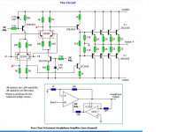
I've attached the constant current source servo circuit from the Gilmore headphone amp. Some Krell Klone designers may want to Spice experiment on similar circuits. Some amp designers say they can hear a loss of dynamics with a traditional voltage summing servo, and a constant current souce servo would be sonically superior if a robust design can be worked out.
Attachments
Perhaps Jacco thought Mark's spelling of Wiki was incorrect, or perhaps he thought PinkMouse had left too much pink slime on the past pages of this thread in locating a fast link to this Wiki.
I know earlier, I had to dig through the backpages to find it myself.
Now it is off to the barber. Mark knows I have an important date!
😉
I know earlier, I had to dig through the backpages to find it myself.
Now it is off to the barber. Mark knows I have an important date!
😉
Hi PWatts,
I've attached the constant current source servo circuit from Steve. Some Krell Klone designers may want to Spice experiment on similar circuits. Some amp designers say they can hear a loss of dynamics with a traditional voltage summing servo, and a constant current souce servo would be sonically superior if a robust design can be worked out.
I've attached the constant current source servo circuit from Steve. Some Krell Klone designers may want to Spice experiment on similar circuits. Some amp designers say they can hear a loss of dynamics with a traditional voltage summing servo, and a constant current souce servo would be sonically superior if a robust design can be worked out.
Attachments
Hi all,
I've cobbled a servo together (in theory though) that simulates well with the KSA100. It's a normal lowpass summing one, but a dual-stage one that works a bit better. It's fairly simple with one dual opamp, four capacitors and five resistors per channel. This is excluding the opamp power supply, but can be downregulated with a standard zener and elementary decoupling.
The simulations are promising, and (as one would expect) it didn't do anything to the THD. It also allows one to leave out R17-R21, D3-D4 and VR2, and this reduces the distortion somewhat.
Since component quality isn't too important, this could be assembled on a very small PCB using SMD components, easily smaller than 40x40mm. Experimenting is also easy; it only needs two leads from the amp. If it works, R19 can be removed and if successful the rest of the original DC correction components too.
The Gilmore servo is an interesting one.. I've used it myself on a headphone amp design of my own a few years ago but never for power amps. I'll toy around a bit with some of the current-source servo's too sometime, but the moment it becomes complex it will be increasingly difficult to use as add-on for existing boards. However, since even they are simple to build and test there's no reason why people can't experiment with it by themselves.
- Home
- Amplifiers
- Solid State
- Krell KSA 100mkII Clone