Hello,
My KRELL KAV280cd is faulty !
The problem :
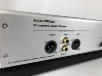
- digital outputs, coax & optics are OK,
- analog outputs, coax & XLR, left & right are wholly
dead.
Power supply is OK : +/-18v +/-5v ...
Then, I suspect one issue on :
- digital filter board,
- or on DAC board
My problem, for understanding and repair :
- I have no schematics, no sm
Truly, I would appreciate if you could help me
Raymond
( pardon my English ! )
.jpg")
.jpg")
My KRELL KAV280cd is faulty !
The problem :
- digital outputs, coax & optics are OK,
- analog outputs, coax & XLR, left & right are wholly
dead.
Power supply is OK : +/-18v +/-5v ...
Then, I suspect one issue on :
- digital filter board,
- or on DAC board
My problem, for understanding and repair :
- I have no schematics, no sm
Truly, I would appreciate if you could help me
Raymond
( pardon my English ! )
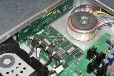
First step is to check all supplies at their destinations as this player is sure to have multiple rails. Check the supplies on those stand up boards.
Are those relays operating (the relays could be for muting) ? Use a scope and see if there is audio on one side of the relay.
If not, then locate the DAC, ID the chip used, get the data sheet and see if audio is emerging from the DAC. If the DAC feeds an I/V convertor (typically an opamp) then look for audio on the output of that opamp.
MOOLY !
Thank you very much !!
Very good analysis for attack the problem.
The difficulty is that the tracks are below, so very difficult to measure.
Your idea to take DAC output is good.
I wait to see if someone might have patterns, which greatly facilitate.
Raymond
Thank you very much !!
Very good analysis for attack the problem.
The difficulty is that the tracks are below, so very difficult to measure.
Your idea to take DAC output is good.
I wait to see if someone might have patterns, which greatly facilitate.
Raymond
Hello MOOLY,
Thanks again for your help !!
Because :
- digital Outputs is OK,
- Analog Outputs L&R are dead,
- supplies are OK
Fault can only located on :
- Digital Filter board,
- DAC board,
- or 4 relays are no activated.
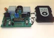
On Digital Filter board, there is :
- U1 = BB DF1704E
- U8 = TI 99ADORM HC04 ( I don't know what it is ! )
- U2 = MC34064P
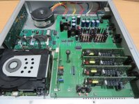
On DAC board, there is :
- U1 to U4 = BB PCM1704
Below some pics for You :
- Digital filter board face & reverse,
- DAC board face &reverse
Yours,
Raymond
 R.jpg")
 R.jpg")
 R.jpg")
 R.jpg")
Thanks again for your help !!
Because :
- digital Outputs is OK,
- Analog Outputs L&R are dead,
- supplies are OK
Fault can only located on :
- Digital Filter board,
- DAC board,
- or 4 relays are no activated.
On Digital Filter board, there is :
- U1 = BB DF1704E
- U8 = TI 99ADORM HC04 ( I don't know what it is ! )
- U2 = MC34064P
On DAC board, there is :
- U1 to U4 = BB PCM1704
Below some pics for You :
- Digital filter board face & reverse,
- DAC board face &reverse
Yours,
Raymond
Here's the data sheet for the PCM1704 DAC.
HTTP 301 This page has been moved
You need to check the two supplies are correct. Pin 14 is the audio output but if it feeds an opamp then you will not see any signal at that point on a scope. You would have to look a the opamp output.
It looks like the Krell is running all these convertors in parallel so you will have to trace pin 14 on one of the chips and see where it goes.
U8 could possibly be a 74HC04 general purpose logic chip.
Philips - datasheet pdf
See if the supply pins match, and check the chip has voltage.
Faults like this often tend to be something basic rather than some weird involved problem.
Faults like this often tend to be something basic rather than some weird involved problem.
Hello MOOLY,
I am coming back after this long time.
And I wish you could be right !!
Then ... :
- Supplies are OK ( +/-5v for digital, +/-18v for audio )
- No problem with capacitors, semiconductors ( BC547, ... ), resistors, soldering, ...,
- if digital outputs are OK, that means Philips VAM1201 is nice working,
- The four Audio PCB must be removed from the list of culprits ( impossible that the four might have a fault simultaneously ),
- It remains Digital Filter Board and DAC Board, to the attention.
Digital Filter Board has 4 outputs to ---> DAC Board
Marked BCKO, WCKO, DOL ( I think "L"= left ) and DOR ( "R" = right )
BCKO oscillogram ( does not vary on pause or play ) :
VCKO oscillogram ( does not vary on Pause or Play ) :
DOL or DOR oscillogram ( on Pause) :
DOL or DOR oscillogram ( on Play ) :
Although I am not a great technician ( what VCKO and BCKO mean !!), I think that reading the DOL and DOR waveforms, the Digital Filter Board should be considered as OK
So, remains the DAC PCB ! More so as, from it, nothing comes out
Please, what do you think ?
Raymond
Attachments
-
 Digital filter board outputs - pin BCKO ( play or pause condition ) R.jpg122.4 KB · Views: 761
 -
 Digital filter board outputs - pin WCKO ( play or pause condition ) R.jpg136.6 KB · Views: 706
 -
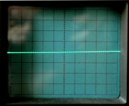 Digital filter board outputs - pins DOR or DOL ( pause condition ) R.jpg112.5 KB · Views: 650
 -
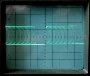 Digital filter board outputs - pins DOR or DOL ( play condition ) R.jpg137.6 KB · Views: 669
Some of the terminology can be a bit hard to decipher but it looks like BCKO (maximum bit clock) will be the main master clock input to the DAC's, the other waveform (the much lower frequency squarewave) looks more like the word or frame clock.
Without a circuit its tough going...
I would look at the data sheet for DAC that I linked to earlier and make sure these signals are arriving. Look at figure 3 in the data sheet. You need those three signals to be present (top left of fig 3). If that's OK then look where 'Iout' from the DAC goes. Its probably an opamp used as an I/V convertor. See if you can pick up audio on the output of that opamp.
Without a detailed circuit its all guesswork though.
Without a circuit its tough going...
I would look at the data sheet for DAC PCM1704...
Look at figure 3 in the data sheet. You need those three signals to be present (top left of fig 3). If that's OK then look where 'Iout' from the DAC goes. Its probably an opamp used as an I/V convertor. See if you can pick up audio on the output of that opamp.
Hi MOOLY,
I will do as you said.
Sure now :
- no problem with continuity ( from Digital Filter Board outs ) for BCKO, WCKO, DOL & DOR ; 3 signals are present on the DAC Board at the entry of the 4 PCM1704 ( pins 2, 7 & 1 ),
- but only with one of the 4 PCM1704 ( ic U1 ) I find "Iout" OK ( pin 14 ),
- for U2, U3 & U4, no signal "Iout".
- there is no opamp after these 4 DAC. Only the four Audio Boards.
Hence, the most probable conclusion :
- 3 dac BB PCM1704 ( U2, U3 & U4 ) are out,
- unless ( possible ? ) a control circuit ( pins 9 & 10, marked " digital controls ") inhibits the operation of PCM1704 ?
- in the lack of schematic, impossible to be sure.
I think I have better to go for a swim in my pool !!
Thanks again for your help.
Raymond
'Iout' signifies the DAC is most probably intended to work into a zero impedance or 'virtual ground' point created by an opamp. Its a subtle difference, voltage out vs current output but it does mean that normally you would NOT see a changing voltage signal at this point.
So you mentioning Iout from U1 as being OK is a little unusual. This is where a circuit diagram becomes a must. If you really can see audio at that point (and that would certainly be possibly if the DAC were resistively loaded at the Iout terminal instead of using an I/V convertor) then try and follow that and see where it goes next.
Resistive loading of a DAC is one of the tweaks of the audiophile world, but the reality is that the linearity and noise performance is compromised compared to true I/V conversion.
'Iout' signifies the DAC is most probably intended to work into a zero impedance or 'virtual ground' point created by an opamp....
If you really can see audio at that point (and that would certainly be possibly if the DAC were resistively loaded at the Iout terminal instead of using an I/V convertor) then try and follow that and see where it goes next...
Hello MOOLY
I picked up signal 'Iout' ( from DAC PCM1704 pin14 ) on the AUDIO BOARD, at their inputs
And only one dac ( U1 ) of the four gives something.
I think U2 U3 & U4 are dead !
For what reason ?
Because it seems very strange that 3 ics dac can fail !!
Without Krell detailled circuit, impossible to go further !!!
The best will be to consider this CD player as a drive.
In other words, it would not be better than the Philips CD player that uses this mechanism.
My greetings from France,
Raymond
A friend of me say to me several years ago, that all low voltage electrolytic SMD/SMT capacitors are to replace by high quality versions.
Unfortunately, the probability is high that the DAC ICs also have to be replaced, as he has already had this Krell CD player model for repair several times with defective PCM1704, which he then replaced completely together with all the electrolytic capacitors.
From such smd caps without any brand logo a lot of inferior versions on the market.
Why are a brand logo to find on elcap versions with wires and versions without wires - i. e. SMD versions no brand logo in general is to find ?
P.S.: Who can upload a schematic diagram and who know, which philips loader is in use ?
Last edited:
The used loader model is "Short Loader" (ECO-SL), probably MK-3 - also in use in the Philips Model CD753 - go to service manual under
https://archives.doctsf.com/bibliotheque/schemas_par_marque/Philips/CD753_compressed.pdf and the attached pdf files.
from an old brochure (from 2001) of Digital Audio Industrial Supply (DAISY) I have found and copied this description:
Technical information on the Short Loader MK3 from DAISY Laser:
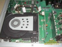
The Short Loader module MK3 consists of a compact tray loader and an electronic board attached under it. A mechanism VAM1201 is enclosed in the loader. The VAM1201 is a modular CD-mechanism, using 2-stage, 3-spot system, and mostly intended for the audio domain.
The application includes the CD decoder and digital servo IC ‘CD7’ (SAA7378, derived from SAA7372) which ensures integrity of audio data retrieved from a disc. This can be achieved because of excellent decoding performances (66MHz data slicer !) and unique error correction system which allows to play back slightly damaged discs (black dots, scratch,…) and compensate for external shocks. The module has successfully passed many playability tests, particularly with low and high reflection discs and test dics with blacks dots and fingerprints.
The Short Loader MK3 can now read CD-ReWritable discs, besides the usual CD-DA (audio) and CD-R discs. CD-R and CD-RW have to be finalised, which means that the TOC (Table Of Content) has been written onto the disc. For this purpose, the Short Loader MK3 has been equipped with the Dalas TDA1302 diode amplifier which has been added to the usual HF amplifier based so far on a HCU04, in order to amplify the reflected signals from the disc (CD-RW discs have indeed a reflectance range of 5 to 20% only). Please, refer to the first issue of the technical bulletin ‘Laser’ for more information on CD-ReWritable technology.
For a superior audio performance, the I²S (or EIAJ) signals (bit clock, word clock and data) are available on a connector and can be used with an external D/A converter. A crystal is now on board in order to ensure an accuracy of +/- 150 ppm minimum (up to +/- 50 ppm) instead of 2000 ppm for the previous ceramic resonator. Such an accuracy allows to use nearly all D/A converters or DA-I/O with optimal performances. Besides, the transmission of the audio data can match the requirements of the external DAC by changing the number of bits, the sample frequency or the audio format by sending a simple software command.
The control interface is based on the DSA standard which allows to easily develop a customised user section, since high-level commands can be used (like play, stop, search…) while all the servo decoding functions are already optimised in a DSA microcontroller. The DSA microcontroller is delivered with the Short Loader MK3 but has to be implemented on the user board. The DSA standard also means that previous user software based on this interface (and consequently the complete user display section) can be used with the Short Loader module MK3. A good solution for evolution of CD systems. More information on the DSA interface can be found in the first issue of the technical bulletin ‘Laser’.
Beside the I²S signals, a digital output is also available on a specific connector. The output format is according IEC958. The crystal accuracy allows a very good transmission. In case of a coaxial output, a digital transformer can be used on the user board.
Since the Short Loader MK3 CD module is based on the standard DSA bus, it can be used with the CD Evaluation Board 2, which can drive any module based on this interface (CD-Pro, Premium 7050, Premium 7051, SL MK2, SL MK3,…).
Differences between MK2 and MK3 version of the Short Loader module
The Short Loader Module MK3 differs from the previous version on the following points which are mostly great improvements related to the audio domain :
ReWritable compatibility is now possible with the SL MK3 because, among other things, of the TDA1302 diode amplifier.
The main clock is based on a crystal (SL MK3) instead of a ceramic resonator (SL MK2), hence improved audio performances. The original accuracy of a ceralock was +/-2000 ppm. The crystal accuracy is now +/-150ppm max. (up to +/-50ppm) which allows to use DAC and DA-I/O with optimal performances.
The DA Converter on board of the module SL MK2 has been removed with the SL MK3. For a superior audio performance, the I²S (or EIAJ) signals are now available on a connector of the new module in order to use an external D/A converter.
The kill output of the CD7 is made available on a connector of the SL MK3 module.
The digital coil of the EBU output has to be implemented on the user board when using the SL MK3, while it could be implemented on the electrical board attached to the SL MK2.
The connectors of the SL MK3 are still JST EH type, but the pin assignments have slightly changed. (A ground signal has been removed from the 9 pins connector of the SL MK2, and a kill signal has been added on the other connector).
Because of the ReWritable compatibility, a new DSA microcontroller is used to control the SL MK3 module. This new DSA microcontroller will automatically be delivered with the Short Loader module MK3.
Hints to remove and replace the Short Loader's tray
During the development or test stages of your CD player, you may want to take the tray apart, for instance to add a tray front panel. However, replacing the tray has to be done carefully, since it may result in mechanical problems which would prevent the application from working correctly.
The tray-switch (white plastic switch at the front of the module) may be wrongly positioned : then, the application would always 'see' the tray in its open state and would refuse to move it. Also, the tray may have been inserted while the position guide was not in its 'open' position. The shift may then result in a wrong estimation of the open and close states, which would lead for instance to close the tray as soon as it is open.
As a conclusion, one should be very careful when removing and especially when putting back the tray in the loader. The following download pdf file provides several hints on how to dismantle (and re-assemble !) a Short-Loader, as well as information to check if the tray mechanism works correctly. It includes several mechanical diagrams which should be useful and definitely time-saving in such circumstances.
P.S.: under
are some URL's removed by moderation.
What was the reason therefore ?
https://archives.doctsf.com/bibliotheque/schemas_par_marque/Philips/CD753_compressed.pdf and the attached pdf files.
from an old brochure (from 2001) of Digital Audio Industrial Supply (DAISY) I have found and copied this description:
Technical information on the Short Loader MK3 from DAISY Laser:
The Short Loader module MK3 consists of a compact tray loader and an electronic board attached under it. A mechanism VAM1201 is enclosed in the loader. The VAM1201 is a modular CD-mechanism, using 2-stage, 3-spot system, and mostly intended for the audio domain.
The application includes the CD decoder and digital servo IC ‘CD7’ (SAA7378, derived from SAA7372) which ensures integrity of audio data retrieved from a disc. This can be achieved because of excellent decoding performances (66MHz data slicer !) and unique error correction system which allows to play back slightly damaged discs (black dots, scratch,…) and compensate for external shocks. The module has successfully passed many playability tests, particularly with low and high reflection discs and test dics with blacks dots and fingerprints.
The Short Loader MK3 can now read CD-ReWritable discs, besides the usual CD-DA (audio) and CD-R discs. CD-R and CD-RW have to be finalised, which means that the TOC (Table Of Content) has been written onto the disc. For this purpose, the Short Loader MK3 has been equipped with the Dalas TDA1302 diode amplifier which has been added to the usual HF amplifier based so far on a HCU04, in order to amplify the reflected signals from the disc (CD-RW discs have indeed a reflectance range of 5 to 20% only). Please, refer to the first issue of the technical bulletin ‘Laser’ for more information on CD-ReWritable technology.
For a superior audio performance, the I²S (or EIAJ) signals (bit clock, word clock and data) are available on a connector and can be used with an external D/A converter. A crystal is now on board in order to ensure an accuracy of +/- 150 ppm minimum (up to +/- 50 ppm) instead of 2000 ppm for the previous ceramic resonator. Such an accuracy allows to use nearly all D/A converters or DA-I/O with optimal performances. Besides, the transmission of the audio data can match the requirements of the external DAC by changing the number of bits, the sample frequency or the audio format by sending a simple software command.
The control interface is based on the DSA standard which allows to easily develop a customised user section, since high-level commands can be used (like play, stop, search…) while all the servo decoding functions are already optimised in a DSA microcontroller. The DSA microcontroller is delivered with the Short Loader MK3 but has to be implemented on the user board. The DSA standard also means that previous user software based on this interface (and consequently the complete user display section) can be used with the Short Loader module MK3. A good solution for evolution of CD systems. More information on the DSA interface can be found in the first issue of the technical bulletin ‘Laser’.
Beside the I²S signals, a digital output is also available on a specific connector. The output format is according IEC958. The crystal accuracy allows a very good transmission. In case of a coaxial output, a digital transformer can be used on the user board.
Since the Short Loader MK3 CD module is based on the standard DSA bus, it can be used with the CD Evaluation Board 2, which can drive any module based on this interface (CD-Pro, Premium 7050, Premium 7051, SL MK2, SL MK3,…).
Differences between MK2 and MK3 version of the Short Loader module
The Short Loader Module MK3 differs from the previous version on the following points which are mostly great improvements related to the audio domain :
ReWritable compatibility is now possible with the SL MK3 because, among other things, of the TDA1302 diode amplifier.
The main clock is based on a crystal (SL MK3) instead of a ceramic resonator (SL MK2), hence improved audio performances. The original accuracy of a ceralock was +/-2000 ppm. The crystal accuracy is now +/-150ppm max. (up to +/-50ppm) which allows to use DAC and DA-I/O with optimal performances.
The DA Converter on board of the module SL MK2 has been removed with the SL MK3. For a superior audio performance, the I²S (or EIAJ) signals are now available on a connector of the new module in order to use an external D/A converter.
The kill output of the CD7 is made available on a connector of the SL MK3 module.
The digital coil of the EBU output has to be implemented on the user board when using the SL MK3, while it could be implemented on the electrical board attached to the SL MK2.
The connectors of the SL MK3 are still JST EH type, but the pin assignments have slightly changed. (A ground signal has been removed from the 9 pins connector of the SL MK2, and a kill signal has been added on the other connector).
Because of the ReWritable compatibility, a new DSA microcontroller is used to control the SL MK3 module. This new DSA microcontroller will automatically be delivered with the Short Loader module MK3.
Hints to remove and replace the Short Loader's tray
During the development or test stages of your CD player, you may want to take the tray apart, for instance to add a tray front panel. However, replacing the tray has to be done carefully, since it may result in mechanical problems which would prevent the application from working correctly.
The tray-switch (white plastic switch at the front of the module) may be wrongly positioned : then, the application would always 'see' the tray in its open state and would refuse to move it. Also, the tray may have been inserted while the position guide was not in its 'open' position. The shift may then result in a wrong estimation of the open and close states, which would lead for instance to close the tray as soon as it is open.
As a conclusion, one should be very careful when removing and especially when putting back the tray in the loader. The following download pdf file provides several hints on how to dismantle (and re-assemble !) a Short-Loader, as well as information to check if the tray mechanism works correctly. It includes several mechanical diagrams which should be useful and definitely time-saving in such circumstances.
P.S.: under
about
Legal
I read follow:
The Website Audio CD Pro - Specialized audio components for the high-end audio market is operated by or on behalf of Digital Audio Industrial Supply, a company registered in France (trading as and referred to as “Digital Audio Industrial Supply” or, where the context admits, “Us”, “We” or “Our”).
It seems to be the mirror page of
Removed by moderation.
with offers especially for small amounts of pieces
Perhaps of interest for diyer's, which planning new cd player projects, so as service departments for jukebox stuff.
- tiefbassuebertr
- Replies: 3
- Forum: Digital Source
What was the reason therefore ?
Attachments
-
Philips DAISY Short Loader (ECO SL) MK-III-II.pdf784.2 KB · Views: 80
-
Philips DAISY Short Loader (ECO SL) MK-III.pdf469.8 KB · Views: 58
-
 Short Loader MK-III VAM 1201 connectors.gif5.9 KB · Views: 67
 -
 Short Loader MK-III VAM 1201 block diagram.gif12.9 KB · Views: 79
 -
 Short Loader MK-III VAM 1201 evaluation kit.jpg8.4 KB · Views: 69
 -
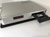
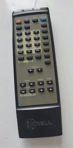 Krell KAV-280cd-rremote contr.webp78.3 KB · Views: 66
 -
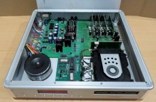
 Krell KAV-280cd-open-V.jpg86.7 KB · Views: 65
 -
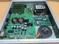
 Krell KAV-280cd-open-IV.jpg97.7 KB · Views: 74
 -
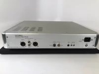 Krell KAV-280cd-rear.webp114 KB · Views: 68
 -
 Krell KAV-280cd-rear-II.webp98 KB · Views: 66
 -
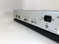 Krell KAV-280cd-rear-III.webp95.5 KB · Views: 63
 -
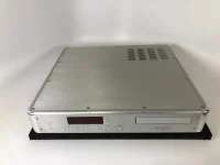
 Krell KAV-280cd-top view.webp88.8 KB · Views: 59
 -
 Krell KAV-280cd-front-III.webp81.1 KB · Views: 57
 -
 Krell KAV-280cd-front-II.webp95.7 KB · Views: 60
 -
 Krell KAV-280cd-front-IV.webp93.8 KB · Views: 51
 -
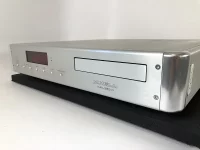 Krell KAV-280cd-front-I.webp23.1 KB · Views: 69
 -
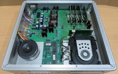
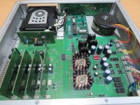 Krell-KAV-280cd-open-VIII.jpg136.4 KB · Views: 70
 -
 Krell-KAV-280cd-open-II.jpg136.8 KB · Views: 60
 -
 Krell_KAV-280cd-open-VI.jpg101.7 KB · Views: 55
 -
 Krell KAV-280cd-open-III.jpg127.9 KB · Views: 68


- Home
- Source & Line
- Digital Source
- KRELL KAV280cd - with issues need help