Any suggestions on what might cause this cdp to not be able to read a disc until it has warmed up for like an hour? The case must be warm to the touch before it will return something other than disc error. I've checked all the board and transport connections and have gone over the PCB's looking for cold solder joints. This thing must be built to MIL-SPEC, very impressive indeed.
If it's anything like other cd players using the Philips cdms, then the usual problems are caused by old electrolytic caps.
If the cdm has the original electronics board, look on it for small , usually blue, caps 33uf.
In any case, replace them with the same voltage and type. Nothing fancy, not bigger, same type. (They are sensitive to change)
Search for CDM error threads (CDM2, CDM4 particularly)
eg. http://www.diyaudio.com/forums/digital-source/40456-cdm2-10-behaving-badly.html
Andy
.
Last edited:
If it's anything like other cd players using the Philips cdms, then the usual problems are caused by old electrolytic caps.
If the cdm has the original electronics board, look on it for small , usually blue, caps 33uf.
Just registered to say thank you

Mine had the exact same symptoms and the 33uF cap was the culprit (only measured 19uF). My friend suffered with this problem since he bought it used in 2008!
In the other CDM thread people were talking about adjusting the pots (one guy said 750, another 243 which is a huge difference). Not sure I needed to go there. The cap was the real fix but I did mess with the pots a bit.
Stefan
Good to hear you have found and fixed the basic issue, however the fact you have altered the pots means that you will have altered the laser power away from its precise value. If you have increased the current then you will be reducing the laser diode life.
Philips were always convoluted in their adjustment procedures and a quick and easy check is just to look at the RF on an oscilloscope and confirm it is within the normally accepted 1.2 to 1.5 volts peak to peak.
Philips were always convoluted in their adjustment procedures and a quick and easy check is just to look at the RF on an oscilloscope and confirm it is within the normally accepted 1.2 to 1.5 volts peak to peak.
I can return to the old R values since I wrote them down. But I am curious, what would be the RF test point for my scope?

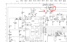
Krell put stickers on all the chips but I can see TDA5709 on the bottom of the optical reader so I assume it’s a 5708 on the same circuit. Unfortunately all the parts are buried underneath and they are surface mount so it will not be possible to measure any voltages while it is playing, unless it’s on the DAC side.
Thank you for your help.
Stefan
Thank you for your help.
Stefan
In practice you should be able to pick the RF up 'by just poking around' with the probe, even if you can't identify specific points... and always use a proper divider probe that is properly compensated. A standard x1 probe has quite a lot of capacitance that can skew the result.
You might also be able to tag a short wire to the point of interest and so connect the probe there.
You might also be able to tag a short wire to the point of interest and so connect the probe there.
- Home
- Source & Line
- Digital Source
- Krell CD-DSP with Philips CDM1 Mk.II issue