Thanks, William
Well noted.
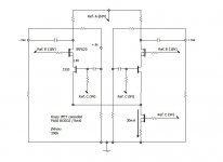
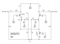
Attached is a brief data about J310 I prepared.
I am thinking the Rd of 1K.
The minimum Gfs of J310 is 0.008mhos.
Min. voltage gain A = Gfs x Rd = 0.008 x 1000 = 8 (18dB)
The maximum Gfs is 0.018mhos.
Max. A = 0.018 x 1000 = 18 (25dB)
Hmmm . . . the gain would be between 18-25dB.
The resistor betweem the output and the input is my "uncertainty." I was unsure about the voltage gain of this concept so that I put my "uncertainty" there in case I need a negative feedback. I will remove it and repost the circuit.
Any other comments . . . ?
Regards
jh
Well noted.
Attached is a brief data about J310 I prepared.
I am thinking the Rd of 1K.
The minimum Gfs of J310 is 0.008mhos.
Min. voltage gain A = Gfs x Rd = 0.008 x 1000 = 8 (18dB)
The maximum Gfs is 0.018mhos.
Max. A = 0.018 x 1000 = 18 (25dB)
Hmmm . . . the gain would be between 18-25dB.
The resistor betweem the output and the input is my "uncertainty." I was unsure about the voltage gain of this concept so that I put my "uncertainty" there in case I need a negative feedback. I will remove it and repost the circuit.
Any other comments . . . ?
Regards
jh
Attachments
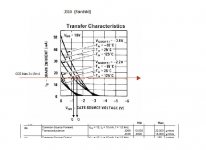
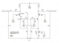
I read data sheet again.
And, re-estimated the voltage gain.
Min. A = 0.011 x 1000 = 11 (20dB)
Max. A = 0.013 x 1000 = 13 (22dB)
Hmm . . . 20-22dB . . .
I wonder if this way of estimation is correct.
So far, nobody seems intersted in or has no time . . .
Regards
jh
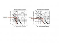
And, re-estimated the voltage gain.
Min. A = 0.011 x 1000 = 11 (20dB)
Max. A = 0.013 x 1000 = 13 (22dB)
Hmm . . . 20-22dB . . .
I wonder if this way of estimation is correct.
So far, nobody seems intersted in or has no time . . .
Regards
jh
Attachments

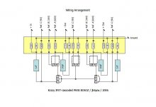
jh6you said:I see . . .
Following this project, I go with JFET-cascoded F1 . . .
Could you please hurry up
I was thinking about the same thing, but due my limited understanding of the world and more specificly mofsets/jfets I need a complete ciruit.

Hurry up . . . ?
The music from F1 is already
 !!!
!!!I do not have the power JFET . . .

Mmm . . . I could create a new thread with a conceptual darwing . . . if the master does not mind . . .
I donnu MOSFET/JFET either, but we are lucky with good supports here . . .
Back to the subject, I am going to try the shown Krazy, 10 days later when I return back to the exciting hell from the boring heaven I am staying now. Still have time for your positive or negative feedbacks.
Regards
jh
Attachments
 Ok ok, I will build the F1.
 I am still waiting for my heatsinks for it, but I should get them soon. All the other parts are already waiting for me on my work table.
I'm sure it will be much better than my gainclones, but I also know that I will have to change it to JFet F1 (or what ever it is goning to be called) when I can.
If one only had the time to learn, but I have so many other projects and a full time job to care of.

 Good luck with the Krazy.
I cannot evalute if it works up to the expectations, but it looks quite interesting. I also do not know if NP officially did something like that already, but I thing you are quite close to the momentary developments at Passlabs. And you have introduced a new name, much better than all those acronyms and number combinations.
Go ahead!
Go ahead!
steenoe said:"The Krazy"
Catchy name
Looking forward for your results, JH
Steen
steen-stop right now!
you have already enough preamps!

I guess you are rightsteen-stop right now!
But I want my share of fun
Even if I had the worlds greatest system, I would still build stuff Cant help it Steen
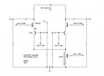
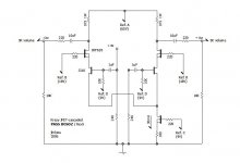
I changed sizes of resistors . . .
Errr . . . Rd is 1.5K//5K//10K = 1K . . .
Soo . . . the voltage gain remains around 20-22dB, approximately . . .
My present status:
My hope at the end: and 
Will see . . .
Regards
jh
---
I feel very sorry whenever I misprint the names of Nelson's children, always with BOSOZ. The title of this thread . . . SOBOZ . . .
Audiofreak, can you kindly correct it into BOSOZ?
Errr . . . Rd is 1.5K//5K//10K = 1K . . .
Soo . . . the voltage gain remains around 20-22dB, approximately . . .
My present status:
My hope at the end:
and Will see . . .
Regards
jh
---
I feel very sorry whenever I misprint the names of Nelson's children, always with BOSOZ. The title of this thread . . . SOBOZ . . .
Audiofreak, can you kindly correct it into BOSOZ?
Attachments
In the cheap advice department, I have usually found it
necessary to put a hundred ohms or so in series with
the outputs to insure that no system oscillation can
occur. There are occasions where even if this circuit
doesn't oscillate, the circuits following might get unhappy.
necessary to put a hundred ohms or so in series with
the outputs to insure that no system oscillation can
occur. There are occasions where even if this circuit
doesn't oscillate, the circuits following might get unhappy.

output impedance
hello jh6you, happy chinese new year to you.
output impedance of your circut will be higher than 1.5K
will it be a problem?
i always think a pre amplifier's out impedance should be less than 1K. or you will reconsider to build a special power amplifier with higher input impedance.
hello jh6you, happy chinese new year to you.
output impedance of your circut will be higher than 1.5K
will it be a problem?
i always think a pre amplifier's out impedance should be less than 1K. or you will reconsider to build a special power amplifier with higher input impedance.
- Status
- This old topic is closed. If you want to reopen this topic, contact a moderator using the "Report Post" button.
- Home
- Amplifiers
- Pass Labs
- Krazy JFET-cascoded Pass BOSOZ