Hi everybody,
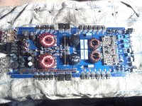
I have a Kove Audio ZD2000V car amplifier that I am trying to repair. Amplifier powers up with protection light on. I've narrowed it down to the power supply section and needing help. Anyone with schematic or troubleshooting ideas please help.
I have a Kove Audio ZD2000V car amplifier that I am trying to repair. Amplifier powers up with protection light on. I've narrowed it down to the power supply section and needing help. Anyone with schematic or troubleshooting ideas please help.
If no one can help, post a photo of the board. It may be a clone of an amp that has a schematic diagram that's readily available.
Generally, when an amp goes into protect mode, the fault is in the audio section. How did you determine that the problem is in the power supply?
Where were the bad solder connections?
Does the power supply try to power up when you apply remote voltage?
Where were the bad solder connections?
Does the power supply try to power up when you apply remote voltage?
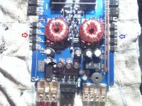
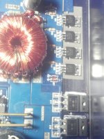
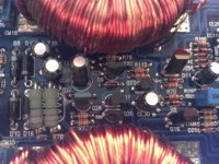
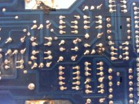
Here's another close up pic of power supply side. Black arrow indicates loose coil. The red side voltage is 1/10th the voltage of the blue side on the 3205's gate pin. I don't have an oscilloscope so all my testing is with a simple multimeter. Not sure if getting right signal from KA7500B controller either. I took the amp to a local repair shop and they confirmed that the power supply was not turning on, but said that without a schematic they couldn't track down the problem without another $200 in labor.
Attachments
Post the DC voltage on all pins of the KA7500. Copy and paste the following into your post.
Pin 1:
Pin 2:
Pin 3:
Pin 4:
Pin 5:
Pin 6:
Pin 7:
Pin 8:
Pin 9:
Pin 10:
Pin 11:
Pin 12:
Pin 13:
Pin 14:
Pin 15:
Pin 16:
Pin 1:
Pin 2:
Pin 3:
Pin 4:
Pin 5:
Pin 6:
Pin 7:
Pin 8:
Pin 9:
Pin 10:
Pin 11:
Pin 12:
Pin 13:
Pin 14:
Pin 15:
Pin 16:
source voltage measured 14.65
Pin 1: 8.44
Pin 2: 2.52
Pin 3: 4.61
Pin 4: 3.75
Pin 5: 1.5
Pin 6: 3.64
Pin 7: 0.0
Pin 8: 14.65
Pin 9: 0.0
Pin 10: 0.0
Pin 11: 14.65
Pin 12: 14.65
Pin 13: 4.94
Pin 14: 4.94
Pin 15: 4.94
Pin 16: 0.0
found a manufacture date of 2003. ran a soldering iron over the spots I thought might be a loose connection and retested with no difference. hopefully this weekend I can get the two 4700uf caps out and checked. saw no leakage but the tops are domed and soft.
thanks for all the help, I DO really appreciate the help!
It appears that the amp is in protect mode. Post the DC voltage on the pins of the 8-pin op-amp adjacent to the ka7500.
The FETs on both sides should have had essentially 0v DC on their gates with the voltages you posted.
The FETs on both sides should have had essentially 0v DC on their gates with the voltages you posted.
Took my measurements there. It is a LM393N.
Pin 1: 9.11
Pin 2: 4.30
Pin 3: 14.20
Pin 4: 0.0
Pin 5: 4.37
Pin 6: 4.40
Pin 7: 9.07
Pin 8: 14.72
Source voltage is 14.75v
Also checked voltages at the capacitors in power supply. I had source V coming into all the smaller caps near input. Did not have anything at the 2 large ones by the large coils.
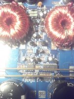
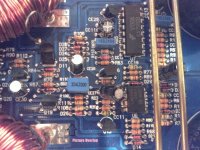
Post a photo of those two ICs and the components immediately around them. It needs to be as clear as possible. Use a real digital camera if you have one.
Here are three more shots of the board. I tried to get two different angles of the chip set and then also one half of the FETs. Hopefully they are good enough was having a hard time with lighting.
Attachments
I was hoping to find a schematic diagram close to the circuit in this amp but with the voltages you posted, none that I have appear to be similar. Do you have a digital camera that will take better photos? If no one else can help, I'd need better photos, including at least one good one of the bottom of the board for the around the KA7500 and LM393.
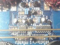
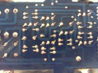
Had an eventfull day. Lighting cooperated so think I got some good pics. Desoldered as many resistors and diodes that I could get to and tested. Everything so far is in tolerances and diodes working properly. Got a few capacitors pulled and getting them tested tomorrow afternoon. This is really turning into an unusual error as haven't been able to find a fault yet.
The pictures are in order of placement on the board. Both top and underside. I labeled the picture overlap.
The pictures are in order of placement on the board. Both top and underside. I labeled the picture overlap.
Attachments
Are there two diodes with their anodes (end without the black band) connected to pins 1 and 7 of the LM393?
If so, do the cathodes of those diodes connect to pin 1 of the KA7500?
If so, do the cathodes of those diodes connect to pin 1 of the KA7500?
pin 1 of the LM393 goes to the cathode side of D31
pin 7 of the LM393 goes to R90, R115, and anode side of D21
pin 1 of the KA7500 goes to R91
R91 goes to R93 which goes to pin 4 of the KA7500
pin 7 of the LM393 goes to R90, R115, and anode side of D21
pin 1 of the KA7500 goes to R91
R91 goes to R93 which goes to pin 4 of the KA7500
This is going to be too time consuming to do this way since it seems to be significantly different than most of the common amps. Have you tried to get the diagram from Kove?
Yeah the company moved to Germany. I tried the last american contact for the company but that site has been idle for years. I got a few more components tested with no new results so put everything back together and put the amp away. Got other projects to work on anyways. Thanks for the help.
- Status
- Not open for further replies.
- Home
- General Interest
- Car Audio
- Kove Audio ZD2000V amplifier schematic?