Enochrome I set the bias in this way. With multimeter Black on GND and red touch careful R9 on the side close Nutube and set the trimmer follow the instruction on post 108 and do the same on R8. Download the pdf on Pete's site to see R8, R9 which trimmer is.
Prove before add 1K resistor. MAybe it's good. I change Q1 and Q3 with 2N4401
Last thing If you like Nelson Design do it but if you buy Pete board and set with Nelson istruction probably the final result it's not good. Choose one or the other.
However Pete's board sound very good.
Regards Stefano
Prove before add 1K resistor. MAybe it's good. I change Q1 and Q3 with 2N4401
Last thing If you like Nelson Design do it but if you buy Pete board and set with Nelson istruction probably the final result it's not good. Choose one or the other.
However Pete's board sound very good.
Regards Stefano
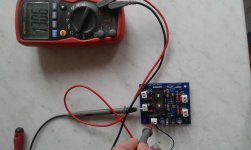
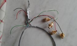
Here are the photos of my build:
I tried reading the schematic but it's over my head. So, if I understand what you saying, is that I put the black on the left or right ground at the output and then the corresponding resistor, either r8or r9 and then adjust the bias with the trim pot with the red lead of the multimeter? When I read the multimeter when adjusting the bias am I seeing the voltage, and the desired outcome would be 1 volt? How can you measure distortion? Is that not possible unless you have an oscilliscope? Shooting for the 1.5 % distortion at 1v that Nelson Pass determined. Thanks again for the help.
An externally hosted image should be here but it was not working when we last tested it.
I tried reading the schematic but it's over my head. So, if I understand what you saying, is that I put the black on the left or right ground at the output and then the corresponding resistor, either r8or r9 and then adjust the bias with the trim pot with the red lead of the multimeter? When I read the multimeter when adjusting the bias am I seeing the voltage, and the desired outcome would be 1 volt? How can you measure distortion? Is that not possible unless you have an oscilliscope? Shooting for the 1.5 % distortion at 1v that Nelson Pass determined. Thanks again for the help.
Measure bias
I do this
With my multimeter I leaves black test lead in gnd every gnd are the same.
1) With red test lead measure the voltage of circuit. In my case is about 13 Volts. See photo
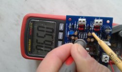
2)With red test lead measure (be careful)the voltage on R9 and set the trimmer R bias until I read 6.50 Volt (13/2=6.5) see photo
3) repeat 2 see photo
If wrong please correct me
I do this
With my multimeter I leaves black test lead in gnd every gnd are the same.
1) With red test lead measure the voltage of circuit. In my case is about 13 Volts. See photo
2)With red test lead measure (be careful)the voltage on R9 and set the trimmer R bias until I read 6.50 Volt (13/2=6.5) see photo
3) repeat 2 see photo
If wrong please correct me

Thanks Volavola! I did what you said and was able to change the voltage to 6.25 because my battery is 12.5. I have not had a chance to add it to my preamp, but I will do so tonight and let you know what the result is.
Also, not sure what happen to my photos but I will fix them soon.
Thanks again.
Also, not sure what happen to my photos but I will fix them soon.
Thanks again.
I wired everything up to my Bent autoformers. Turned on the NuTube, then waited a couple of minutes to power up my tube amp.
Upon powering up, I immediately got a loud buzzing sound so I powered down my amp right away. Tried it again with the same results.
Any ideas what this could be?
Upon powering up, I immediately got a loud buzzing sound so I powered down my amp right away. Tried it again with the same results.
Any ideas what this could be?
Last edited:
Usually it's groun return. What hell is Bent autoformers ? Try before with a simple pot.Check your ground wire. If ground wire ok check the solder joint with a magnifying glass.
Well, I tried checking for ground issues and continuity. Everything seemed fine. I measured the voltage on r8 and r9 and they were both half of the 12.5v. I must have fried a component somewhere because when I wired it up to my other passive pre I got the same very loud buzzing sound. It's a mystery. Thanks for all the help though.
Be quiet. I fried my board too. I invert plus and minus. So now I must solve my mystery. C'mon enochrome we're made to solve the mystery
Anyone tried a cascode with this tube? How much gain and output voltage it could swing before draking the 2/3 HV plate voltage on the upper triode?
I haven't tried it. One thing that complicates circuits other than grounded cathode is the fact that it's a DHT, and also both filaments have a common connection.
I'm thinking that I should make and sell a small isolated DC/DC converter to power the filament to make circuits like that (as well as diff amps, cathode followers, etc.) easier to implement. Good idea?
Pete
I'm thinking that I should make and sell a small isolated DC/DC converter to power the filament to make circuits like that (as well as diff amps, cathode followers, etc.) easier to implement. Good idea?
Pete
Need help getting started with the NUTUBE amp by Pete
Hi All,
Please let me know if this isn't the right forum to ask this.
But if it is, kindly helps a noob with getting started.
I am looking at sourcing NUTUBE amp Board and Tubes from Pete :
NuHybrid Headphone Amp
Without boasting i will say that i consider myself an audiophile but not a DIYphile and am looking to change that considering there are so many good DIY options and you can maintain good quality control.
Ok so coming back to the point, I have basic knowledge of electricals but haven't worked on a breadboard or any kind of soldering since my college days.
1) So if you could provide me a link to an article or tutorial specifically talking about basic stuff i would need to get into DIY.
2) Would appreciate if you can let me know the tools i would need, Preferable from Amazon.in.
3) Some good sources to source components from.
4) A simple project to test the waters before i try my hands on the NUTUBE board.
Would greatly appreciate your inputs here.
Thanks
Finished the headphone amp and have it on my desk at work now. I love the way it fits in the case and shows off the tube and the rest of the workings.
I'm just running it off a dragonfly black and into Sennheiser ear buds so I'm probably not taxing it much but I largely got it for the look and to add an easy to reach volume control on my desk. That and I'm addicted to soldering things.
I could throw out lots of neat words to try to describe the sound but I'll skip that and just say that I've had it on for hours and haven't tired of listening at all. Running just off of the dragonfly I'd tire after an hour or so.
As CoM mentioned the regulator gets quite hot. I can't touch it for longer than a second so I'll be adding a heat sink. With no music playing I do notice a lot of microphony but I don't notice it with the music playing.
Wondering how difficult it would be to add a DAC chipset to the Nutube Headphone amp. I'm leaning towards building this amp - would use it as a desktop amp, but would be a wasted effort to take the audio straight from the sound-card. Could always use an external USB DAC I suppose.
I would very much like to make the tube glow visible via some kind of opening in the front plate, but it might be tricky with the board provided.
I wonder if some form of fiberoptic, or "lightpipe", might allow you to have the affect you want while keeping the actual board back where you want it.
Interested in making a guitar preamp with this. Anyone know of any interesting 6p1 guitar circuits?
There's this five part series: design-of-a-korg-nutube-amplifier
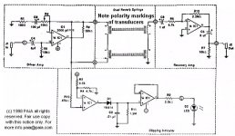
I'd like to build a tube driven spring reverb, like the old Fender units. Would the NuTube be good for this application? I'd be using this circuit, from PAiA, possibly substituting, or adding to, the opamp section.
Attachments
Problems with NuTube buffer
Hi Guys:
I built up a NuTube buffer using Pete's board/tube sourced from ebay and the BOM from Mouser. I used the 2N7000 fet's and 1k ohm resistors in series with the gate (center pin) for Q1 and Q3, and also used 330 Kohm resistors for R8 and R9, as I planned to use this with a 12 v battery.
The build went fine, and after powering, the elements on the tube lit up as expected, and I was able to adjust voltage on the two pots to half the measured voltage of the battery. But, I am getting intermittent popping in the right channel and distorted music on both channels. I have the buffer between a Schiit bifrost multibit DAC, and a Pioneer stereo receiver, which I am using as a preamp, and this is going to a TI TPA 3255 class D amp.
Anybody have any ideas what is going on, or had similar experience? I have other amps I could try with it, too. I'm wondering if running at higher voltage might help, and might try a laptop brick for a power supply of around 19 VDC
Thanks for any help...
limits
😕
Check solder joint. In your pcb and wiring too.
Hi volavola--thanks for the suggestion. I went over everything again with fresh solder, but still get the same behavior from the buffer. It's really odd...it will sound ok for a while, and then when you play some bass-heavy song, I will get a popping sound with the bass beat in the right speaker, then distortion. Wonder if its power supply related. I'm using a 12 volt 9 amp/hour battery. The battery is good, but it almost seems like the board isn't getting enough juice for bass heavy music. Guess I will try a laptop power supply next.
limits
Maybe.
The one I built uses a lot of surface mount components. So it would have to be an assembled module. And I'm not sure I want to do that...
I thought about re-designing it to be all through hole except the class-D chip, then selling the board with the IC mounted. But I'm still undecided if it would sell enough to be worthwhile.
Pete
I'm pretty good with SMT. Would love to put one together
- Home
- Vendor's Bazaar
- Korg NuTube is now available online