SNEAK PREVIEW. Not yet complete (getting closer though)
Add wiring diagrams
Korg Nutube B1 assembly guide
Nelson Pass' original article - http://www.firstwatt.com/pdf/art_diy_nutube_preamp.pdf
NuTube website - Nutube – English | korgnutube.com – English
Pete Millett's NuTube US website - NuTube
Please read though the entire guide before starting.
If the photos are very big now, reload the page and the forum software should resize them. You can then click into them for proper aspect ratio, and then click into the expand button in the lower left to make them very large.
Neatness counts!! 🙂
CHASSIS MECHANICAL AND WIRING
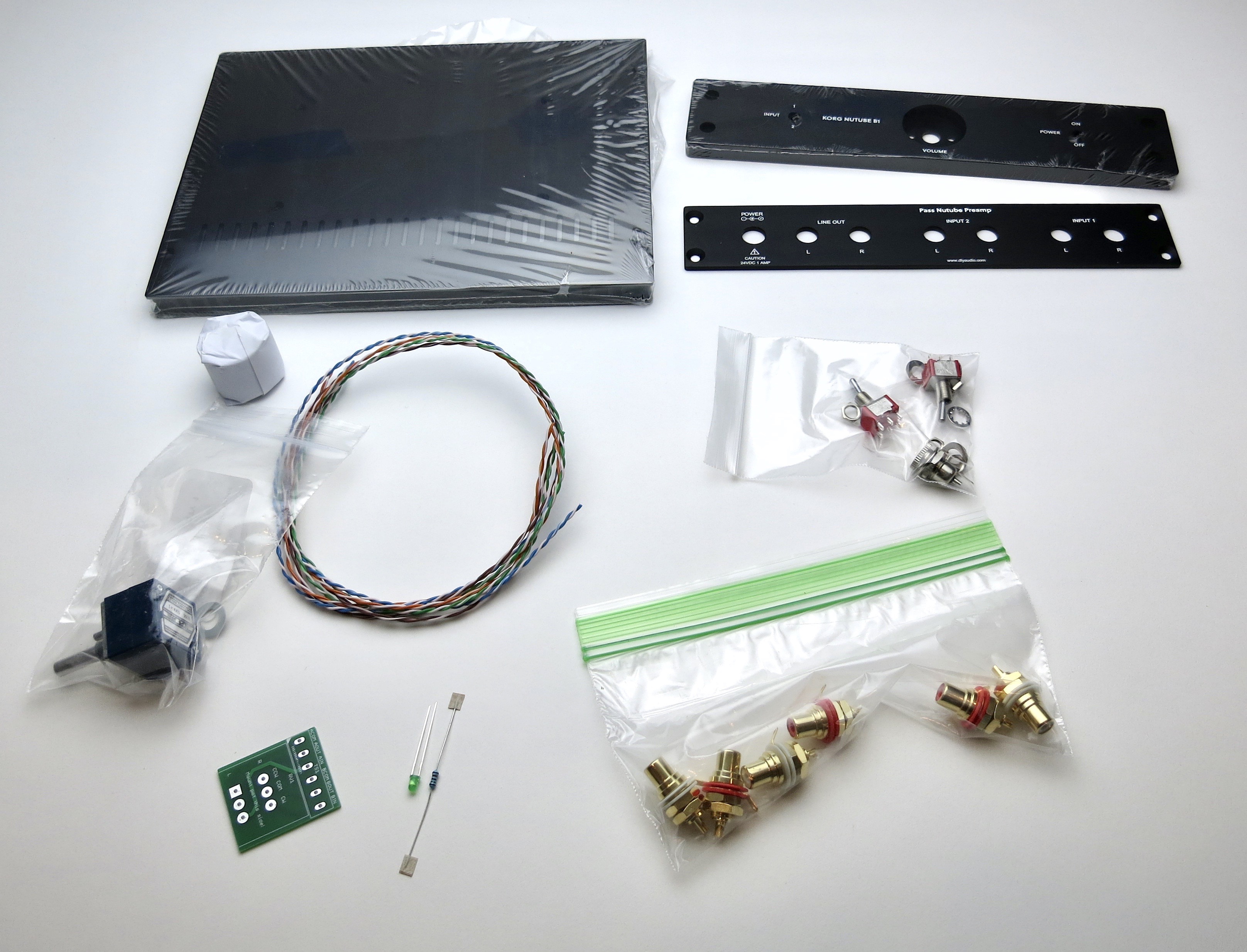
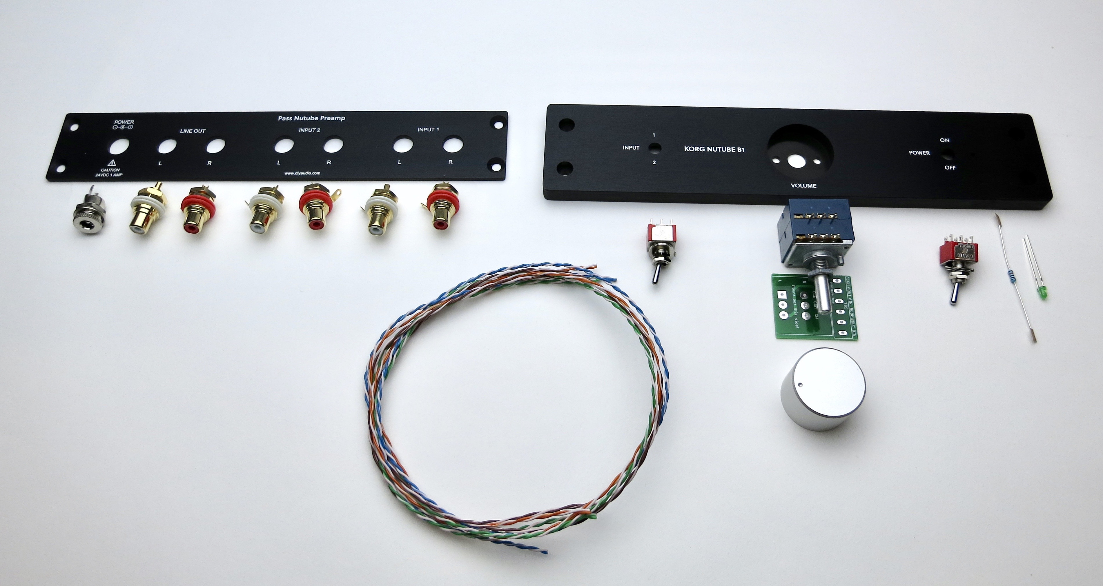
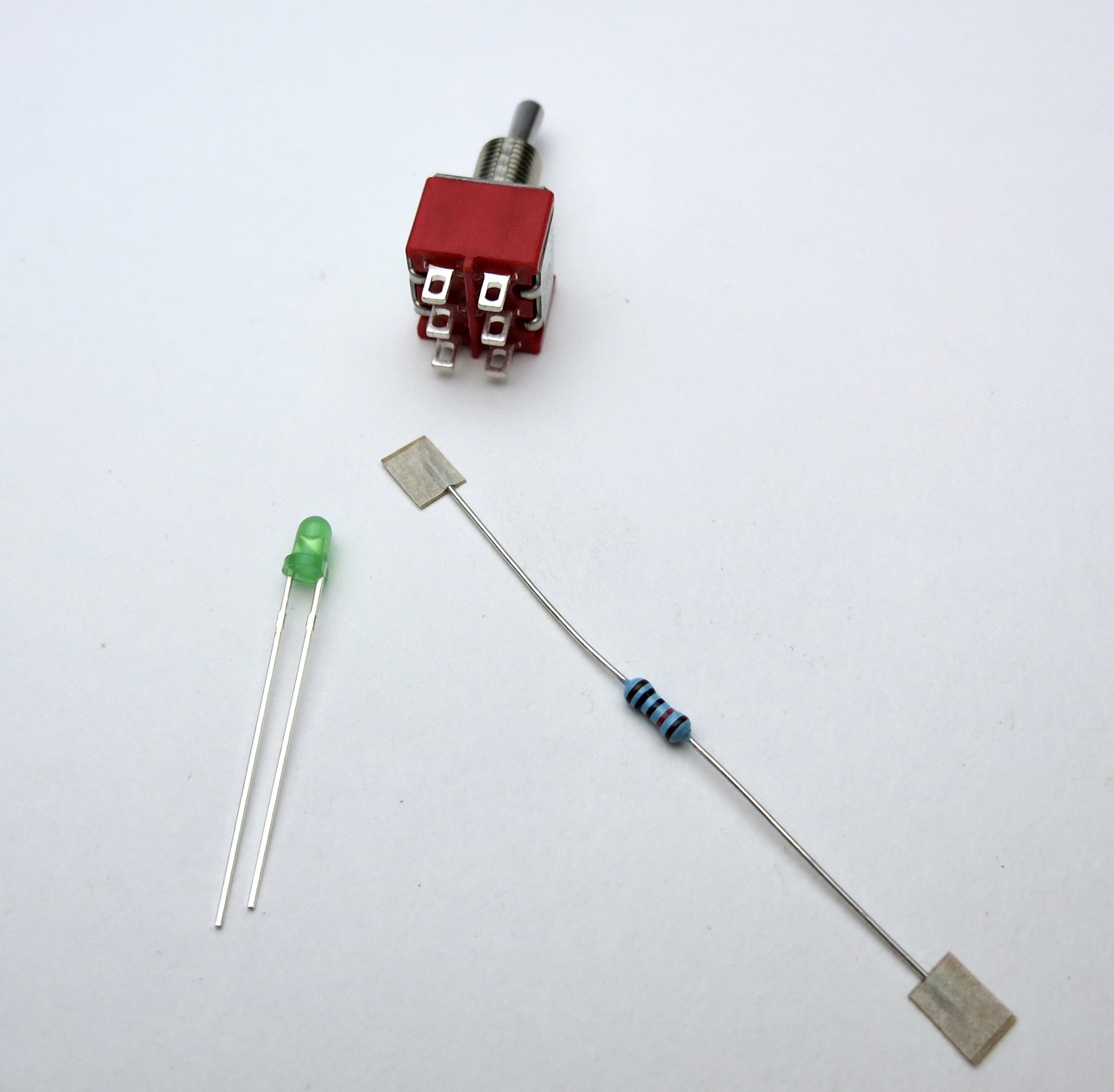
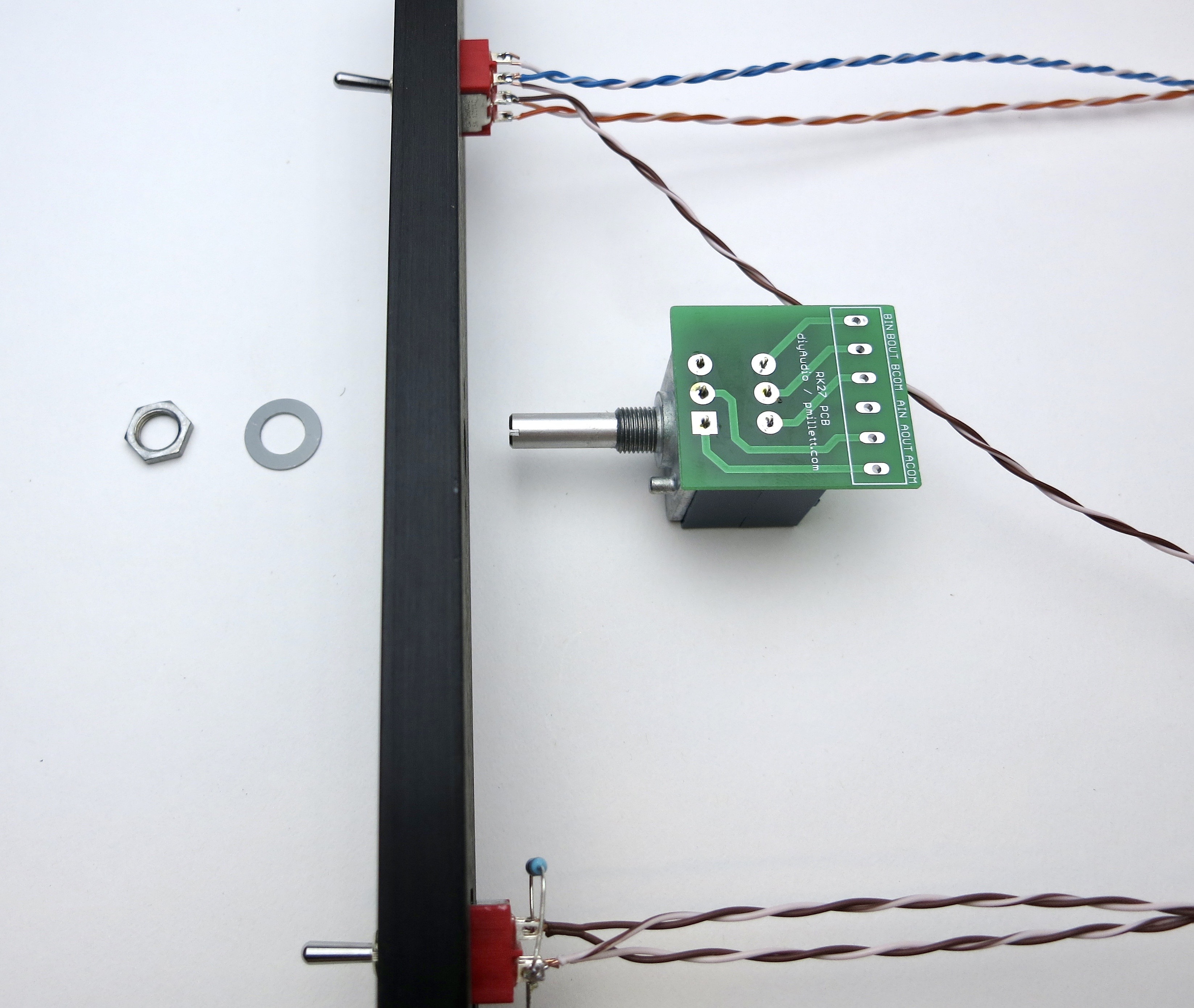
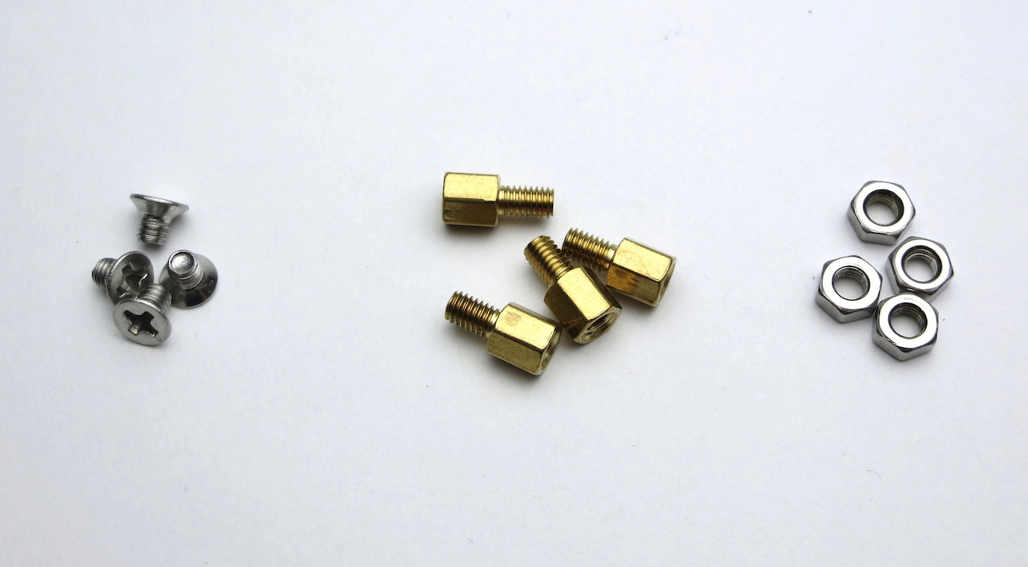
Gather these parts.
(Well, you don't actually need the knob right now... 🙂 )
Note that the toggle switches are identical.
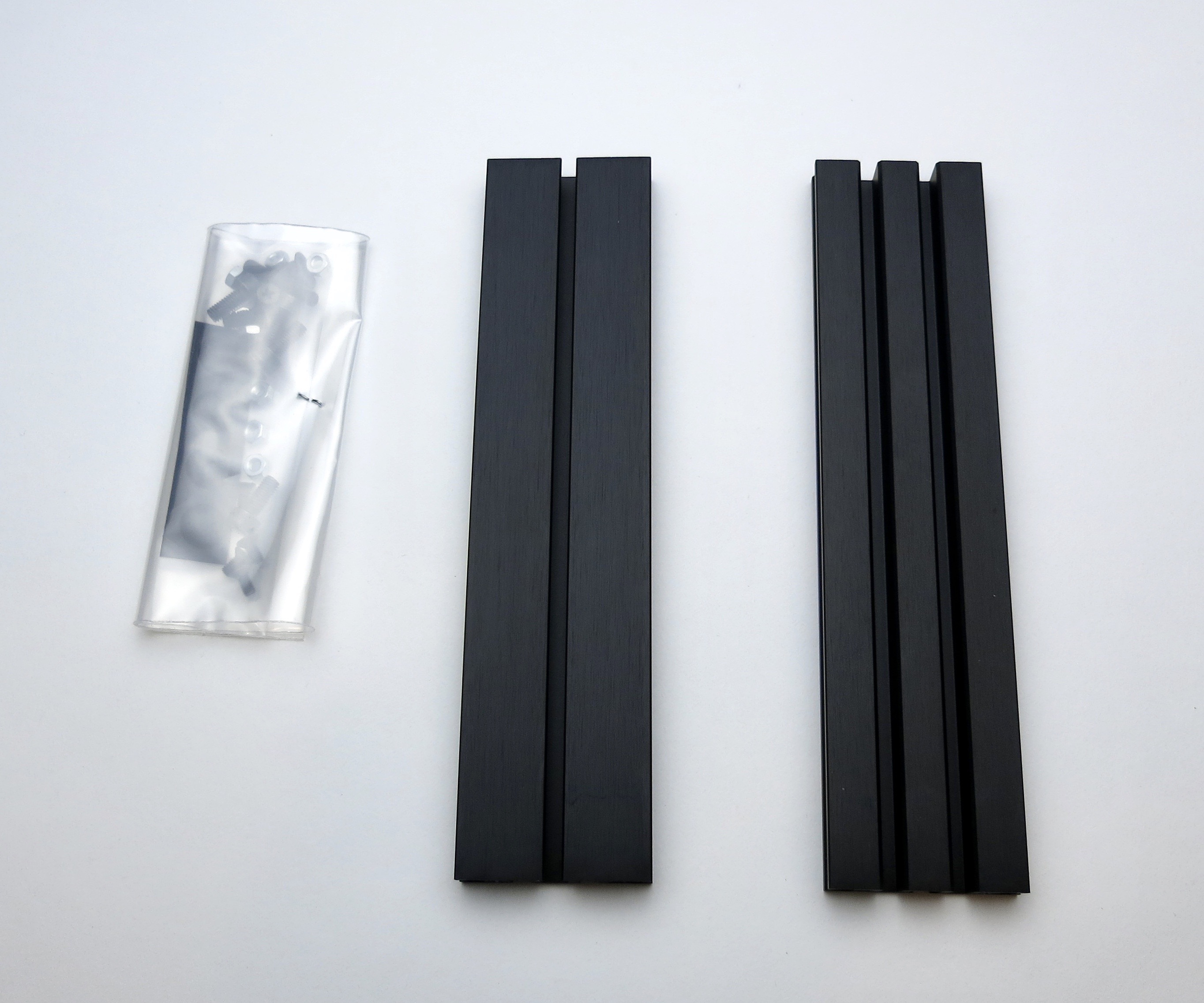
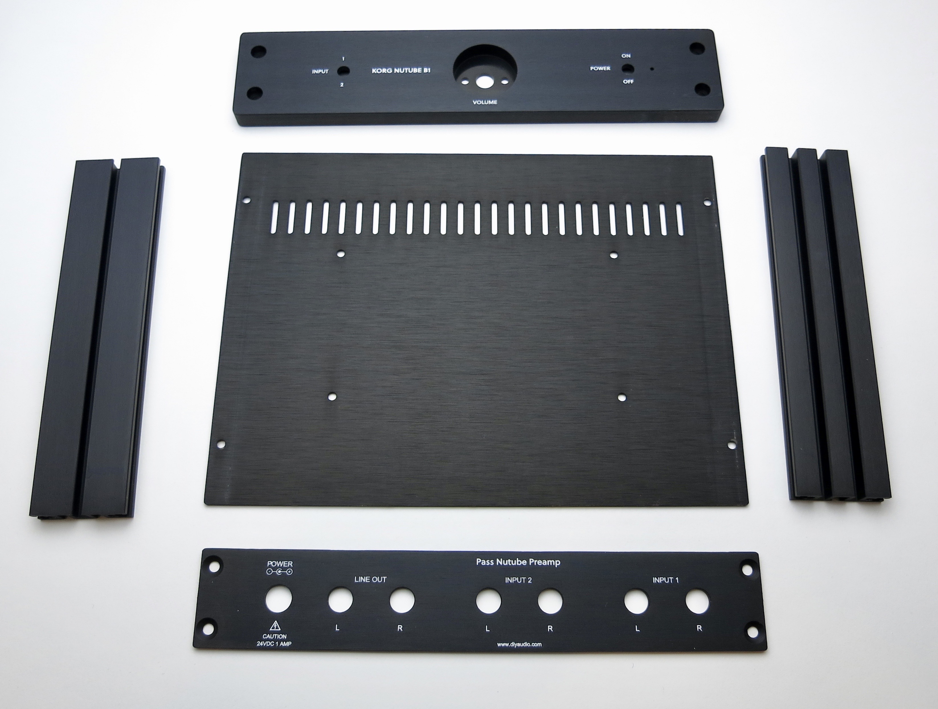
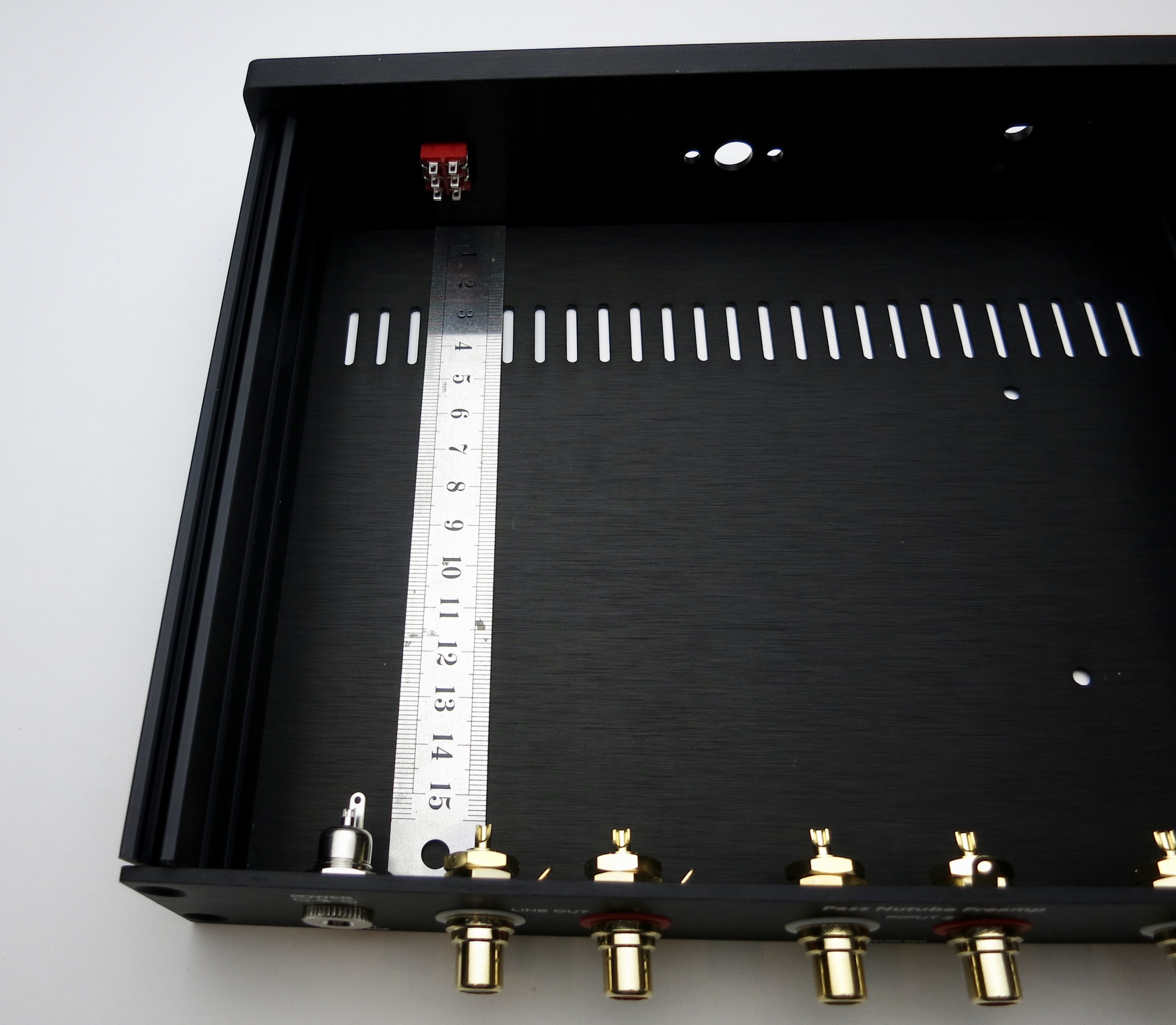
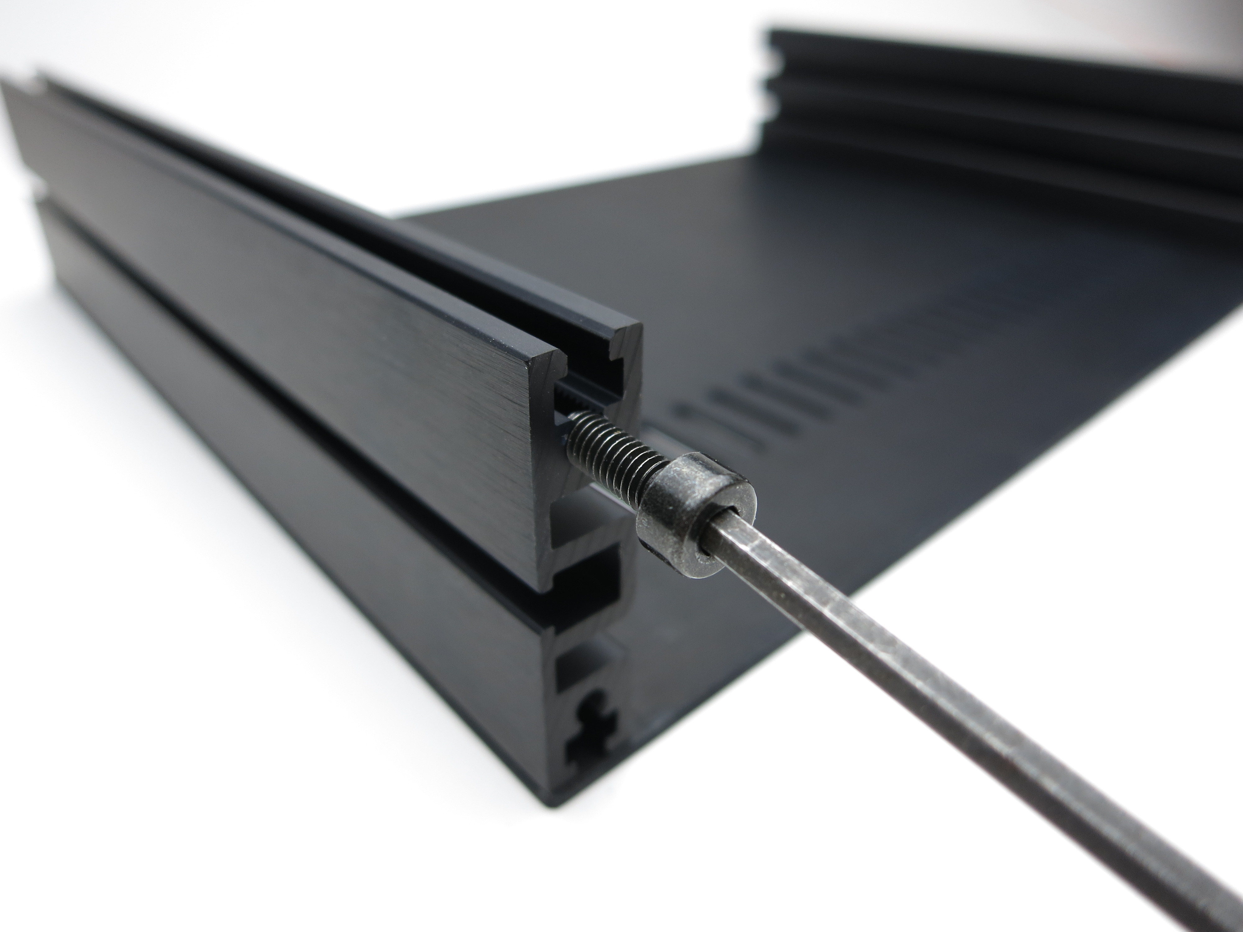
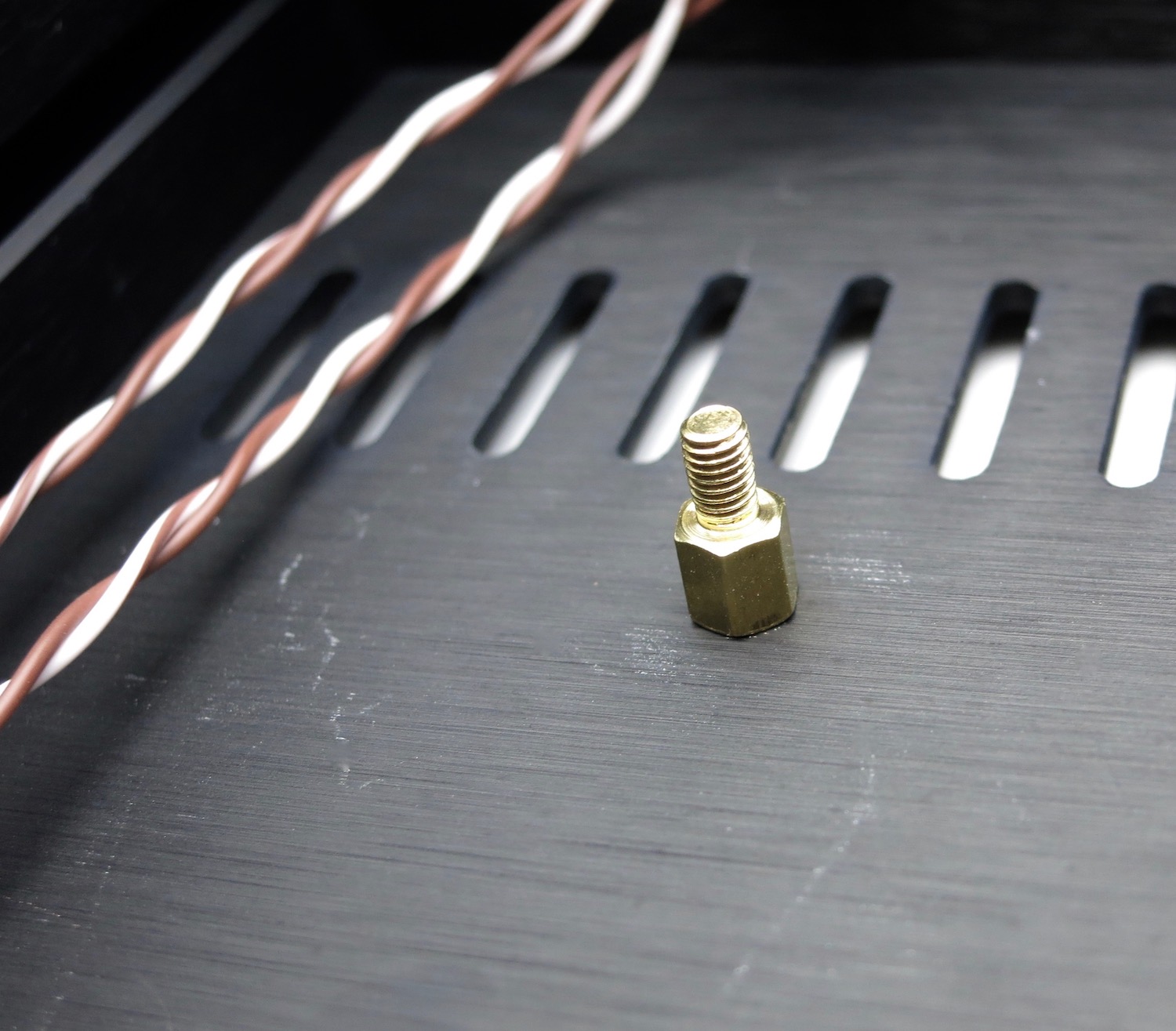
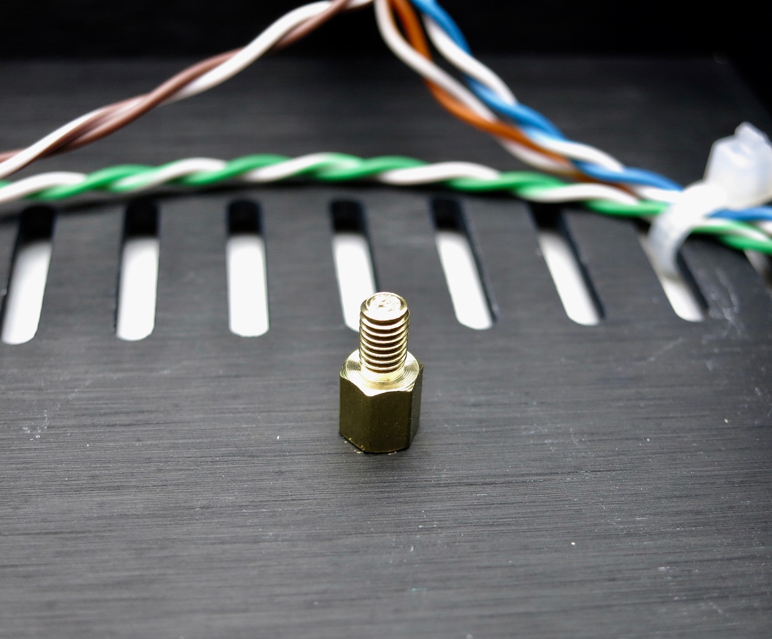
The bottom panel has the 4 holes drilled for the PCB standoffs
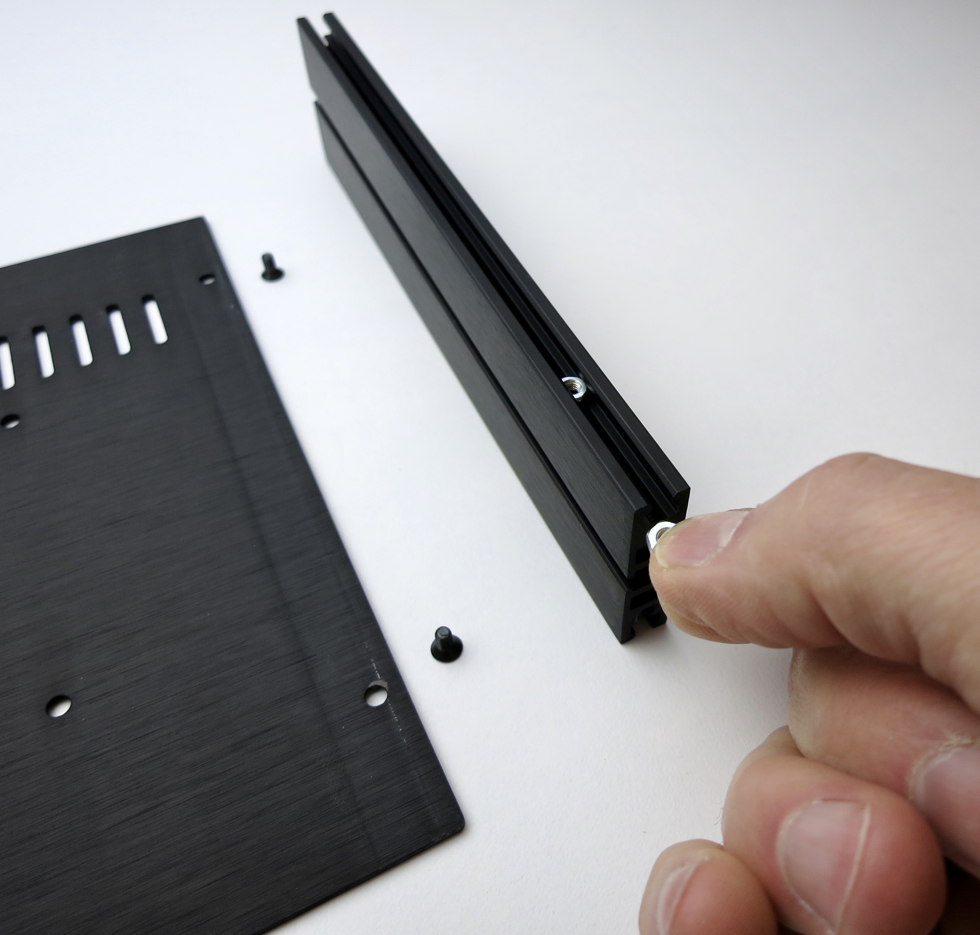
Insert the nuts into the channel
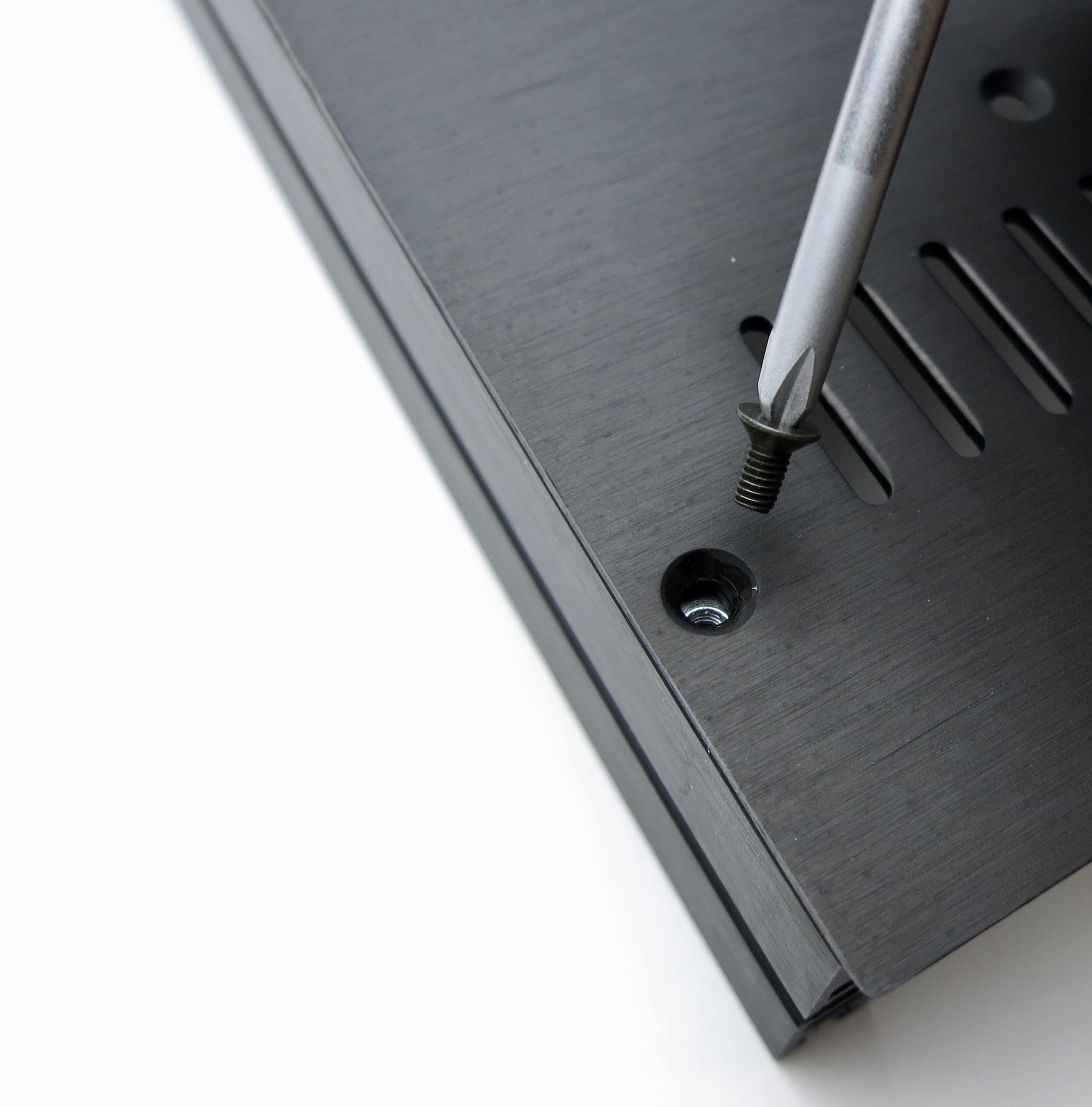
Slide the nuts under the holes then attach the screws
Make sure the holes are aligned with the threaded part of the aluminum extrusion, not the square channel where the nuts go.
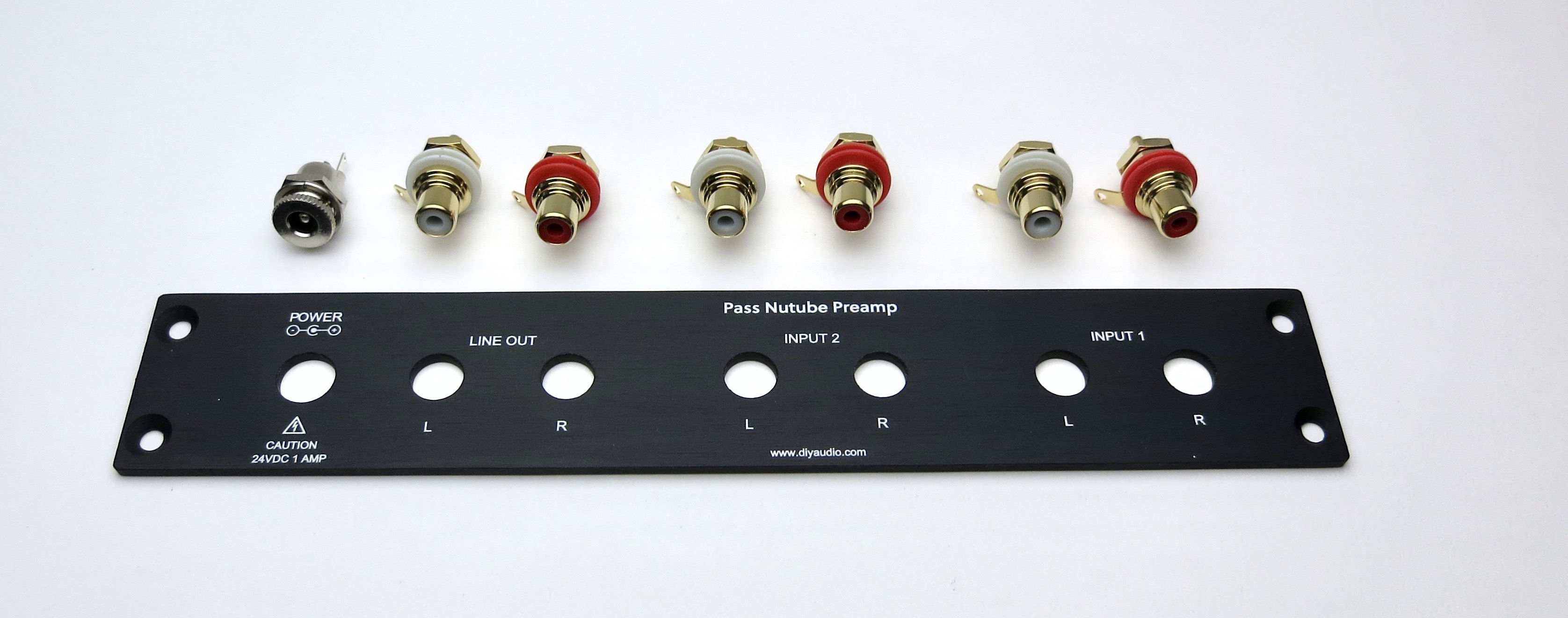
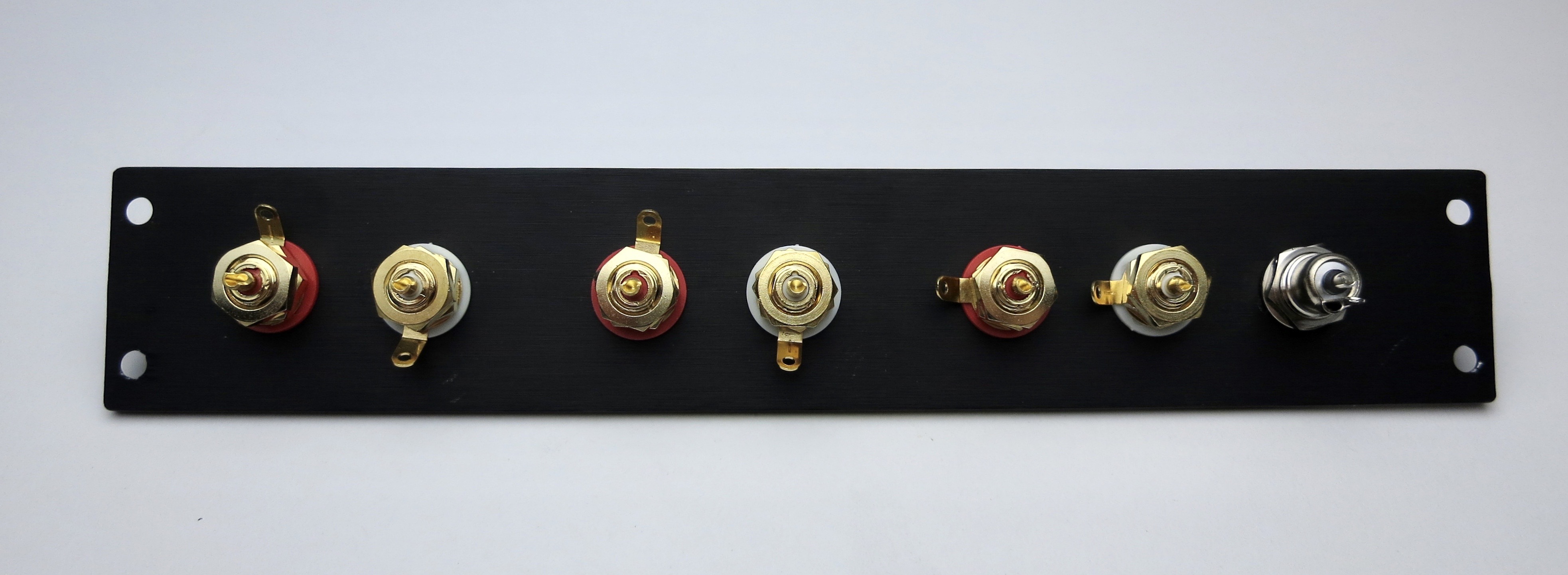
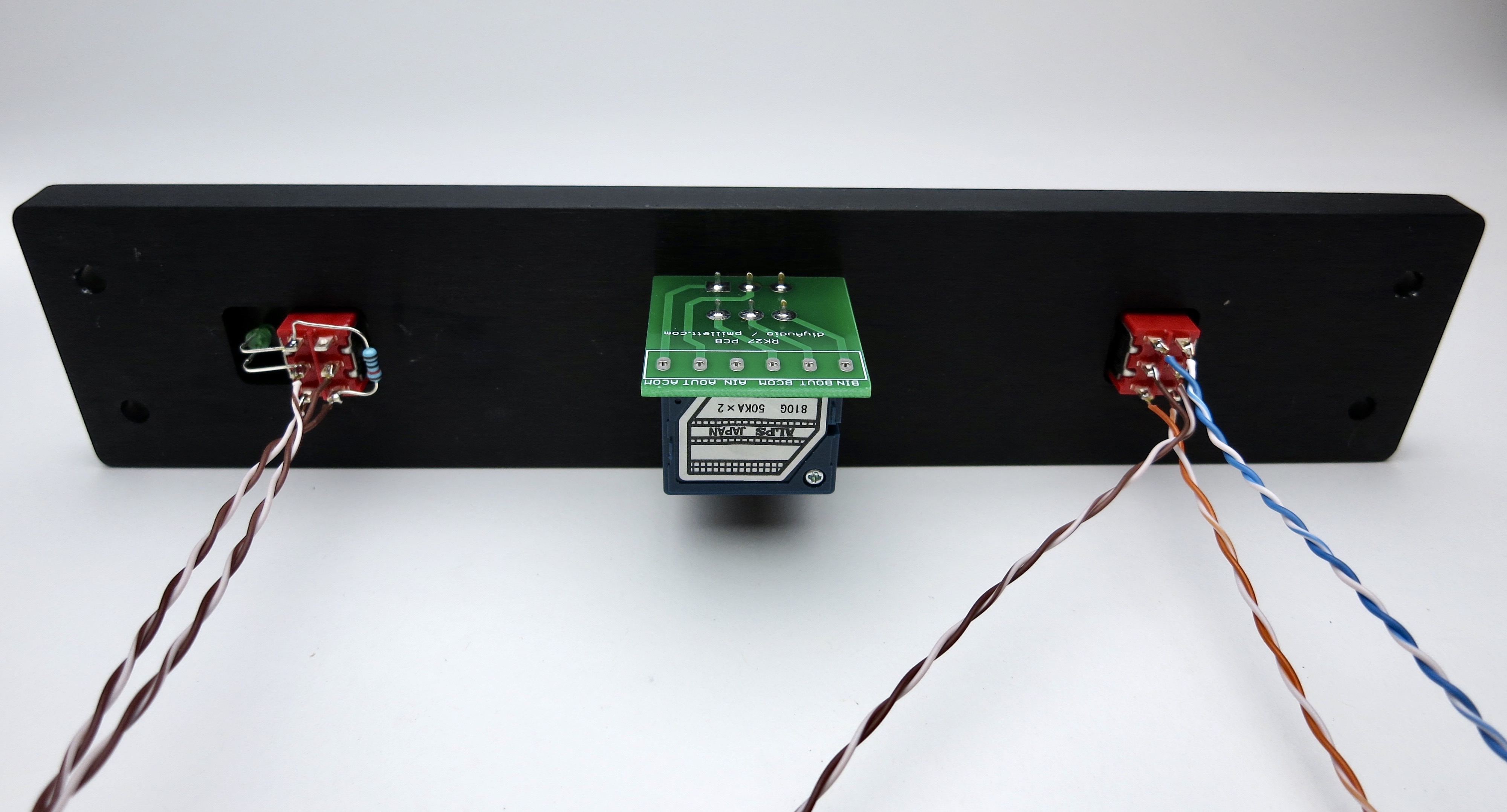
Back panel
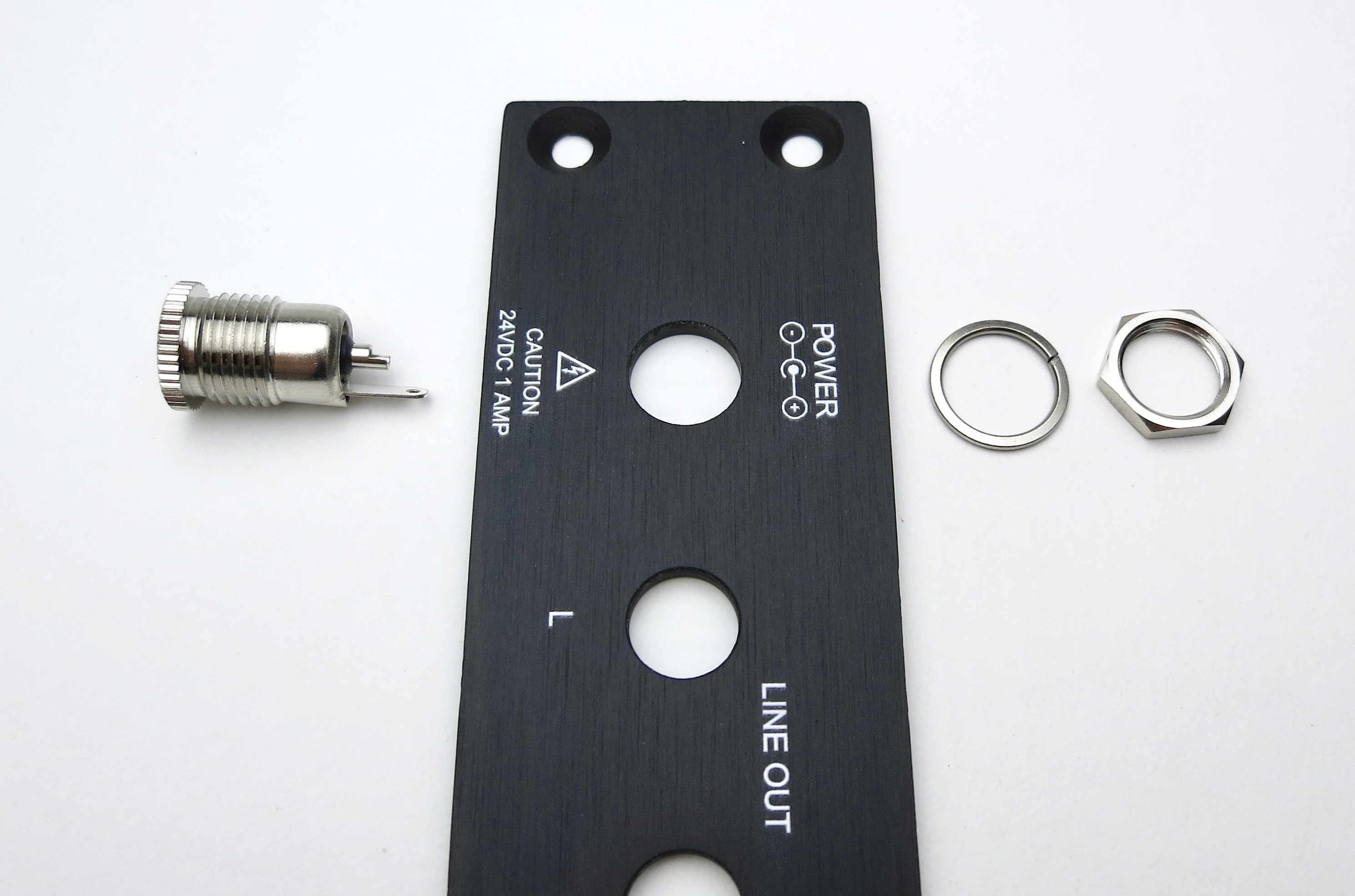
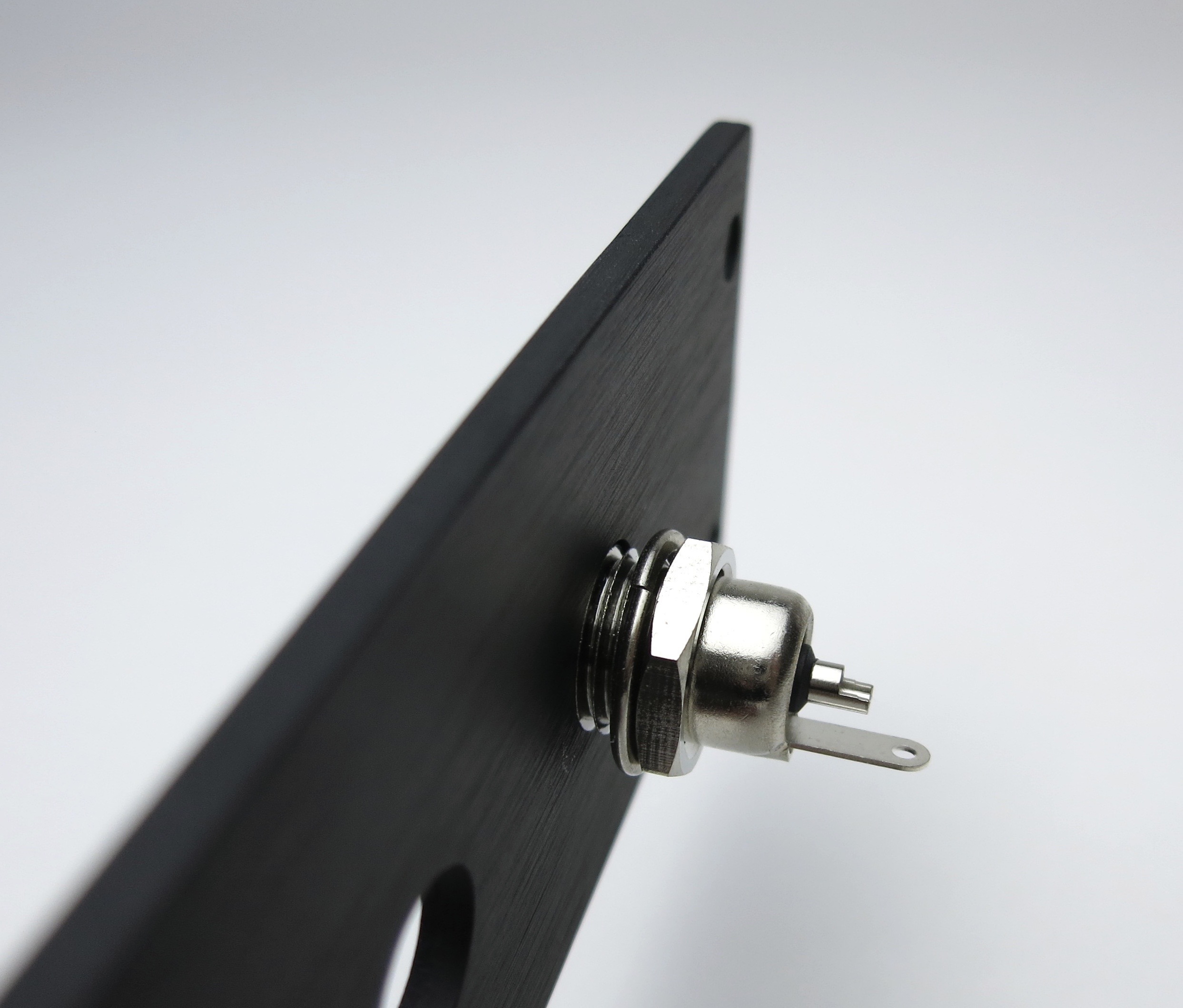
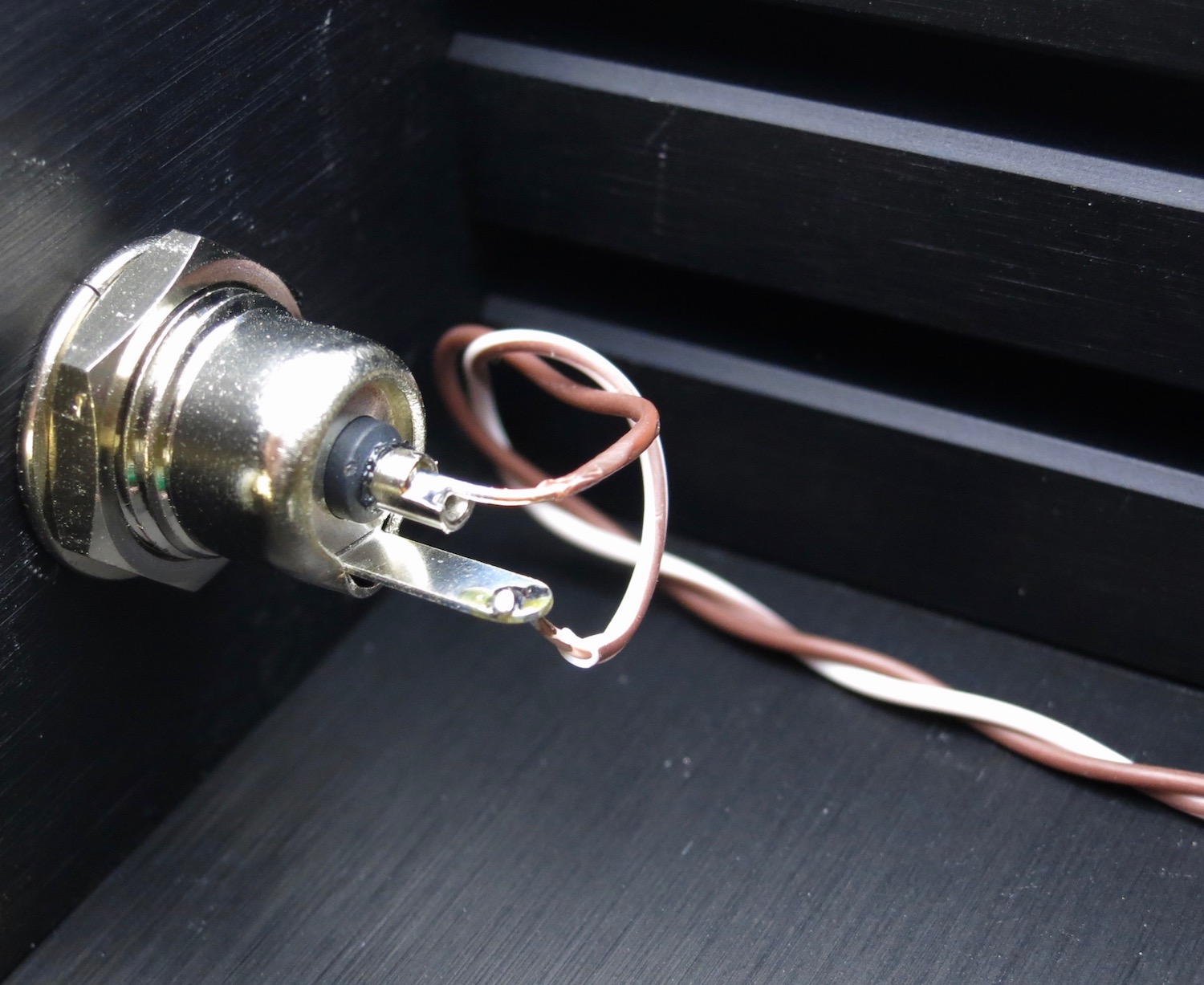
Barrel jack assembly
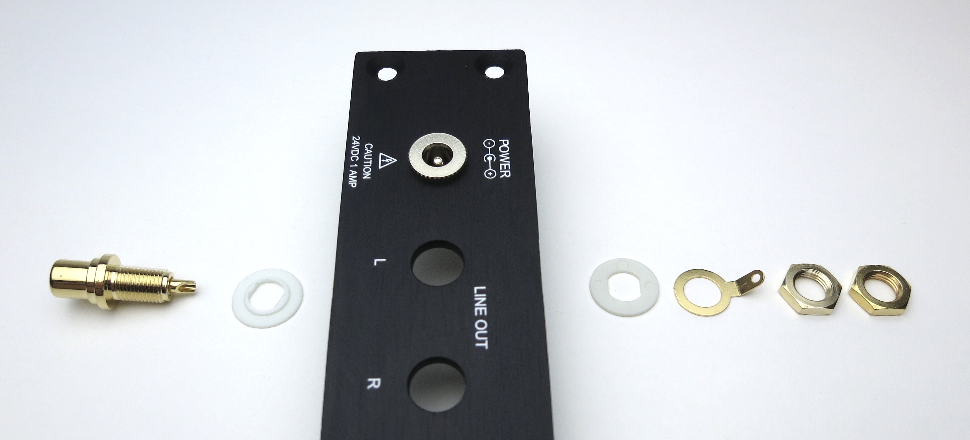
RCA assembly
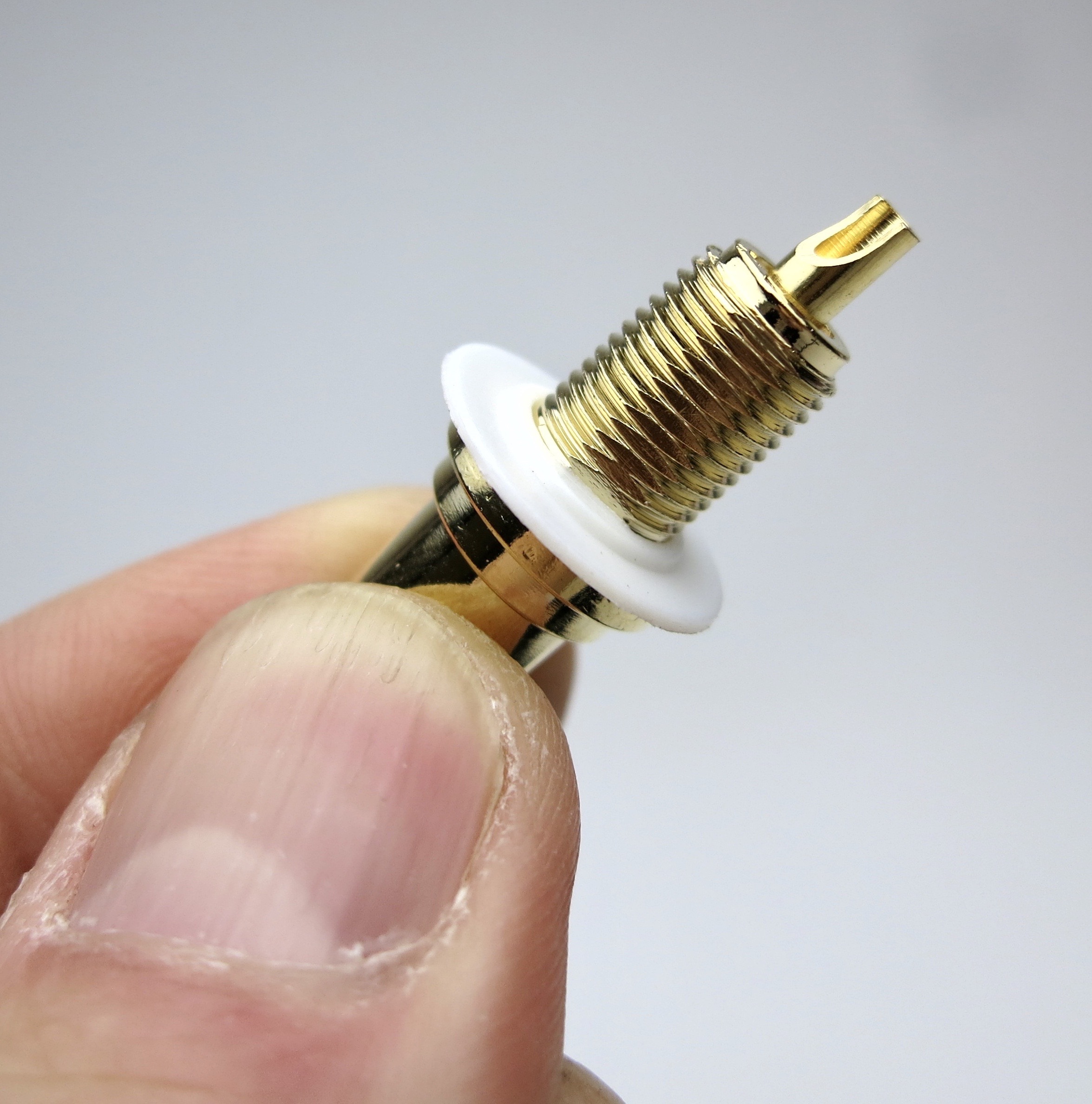
Place the shoulder washer here as shown
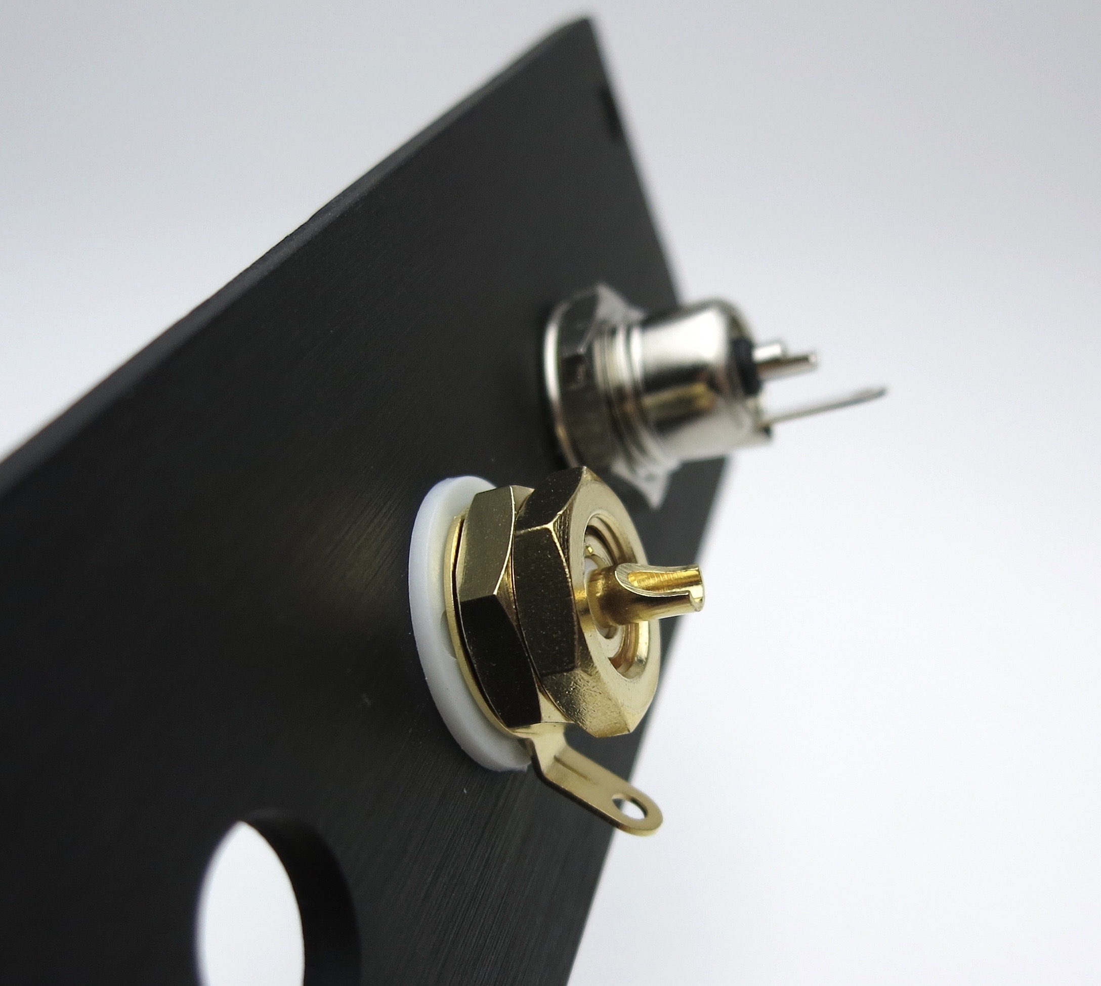
Align tabs as shown
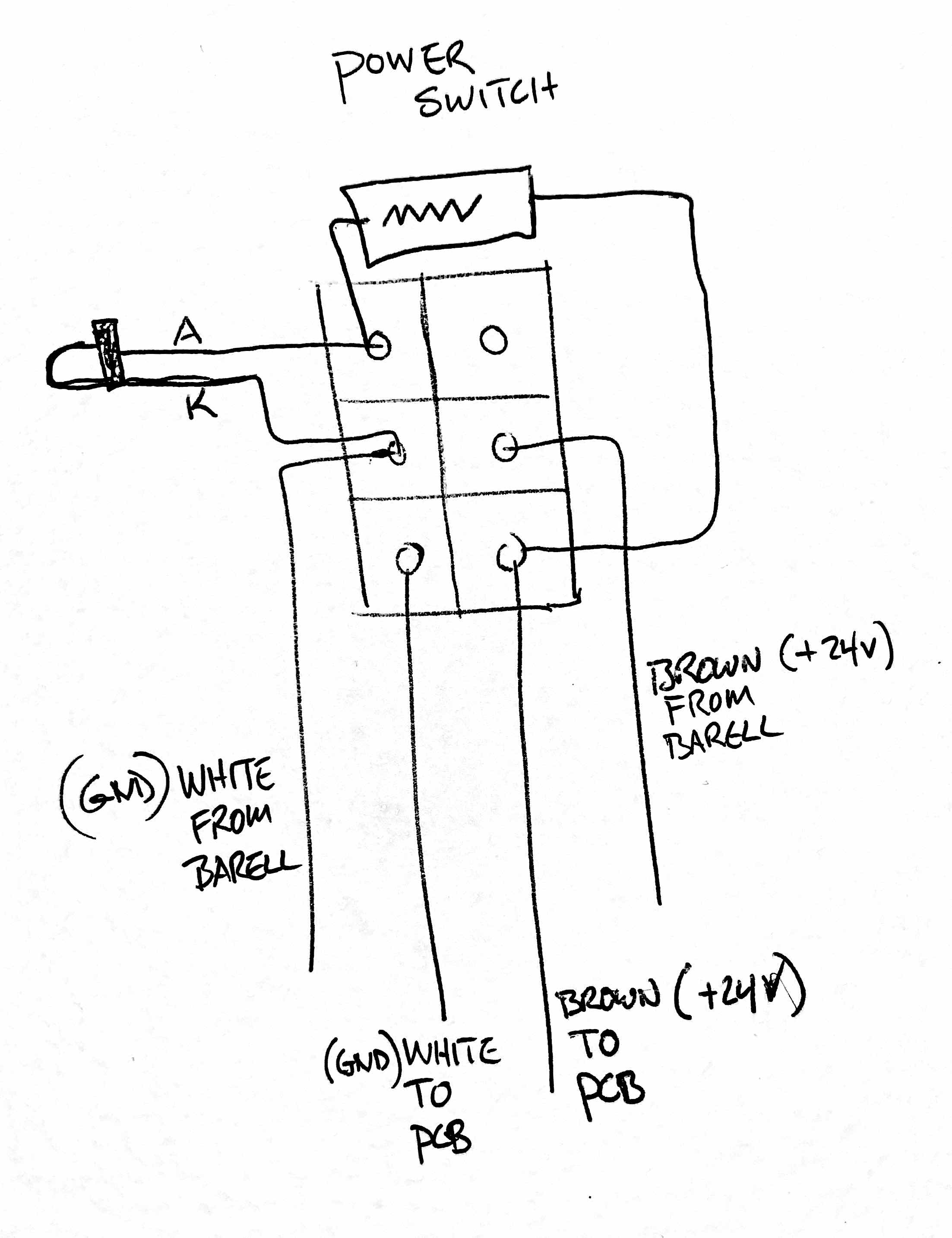
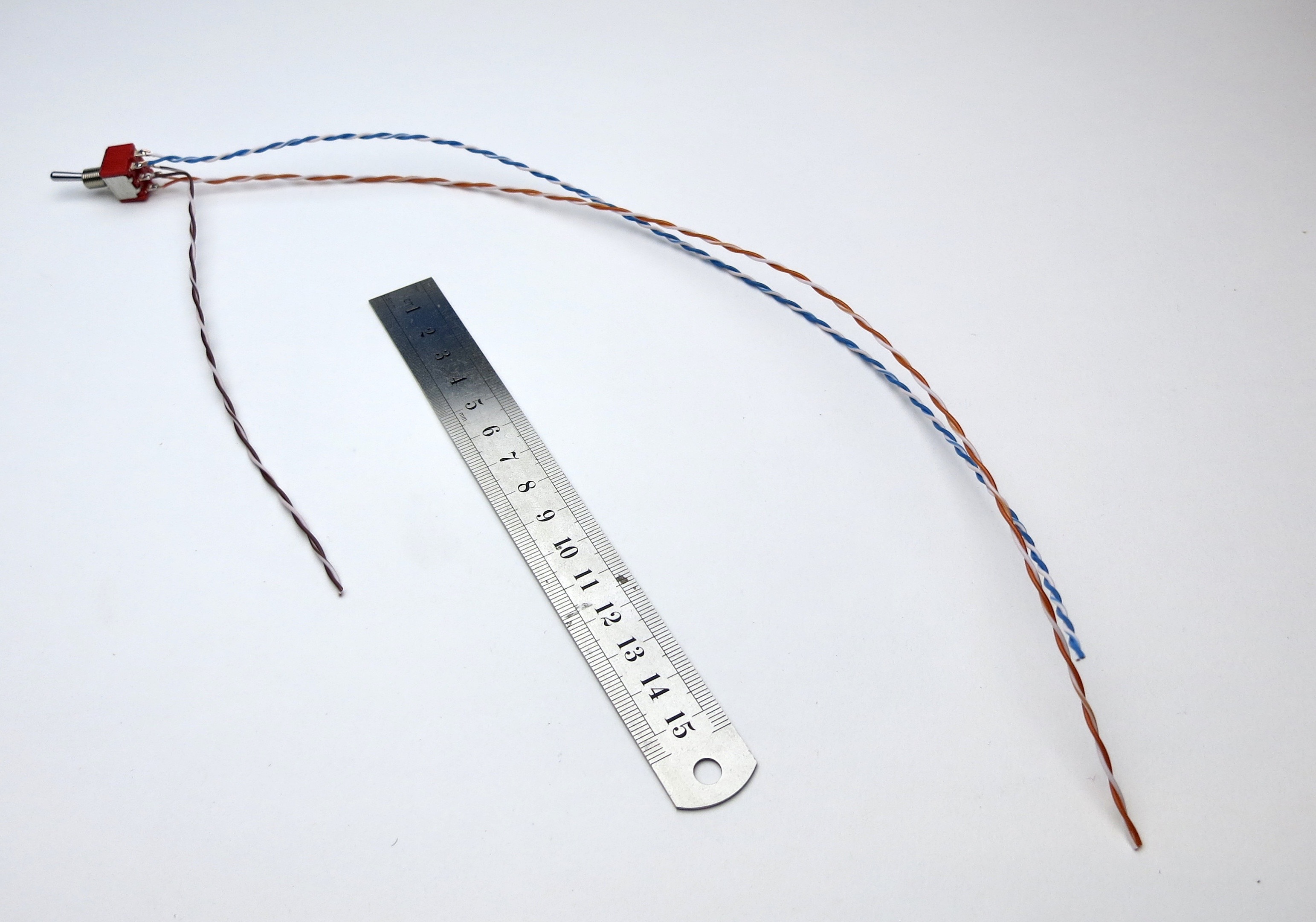
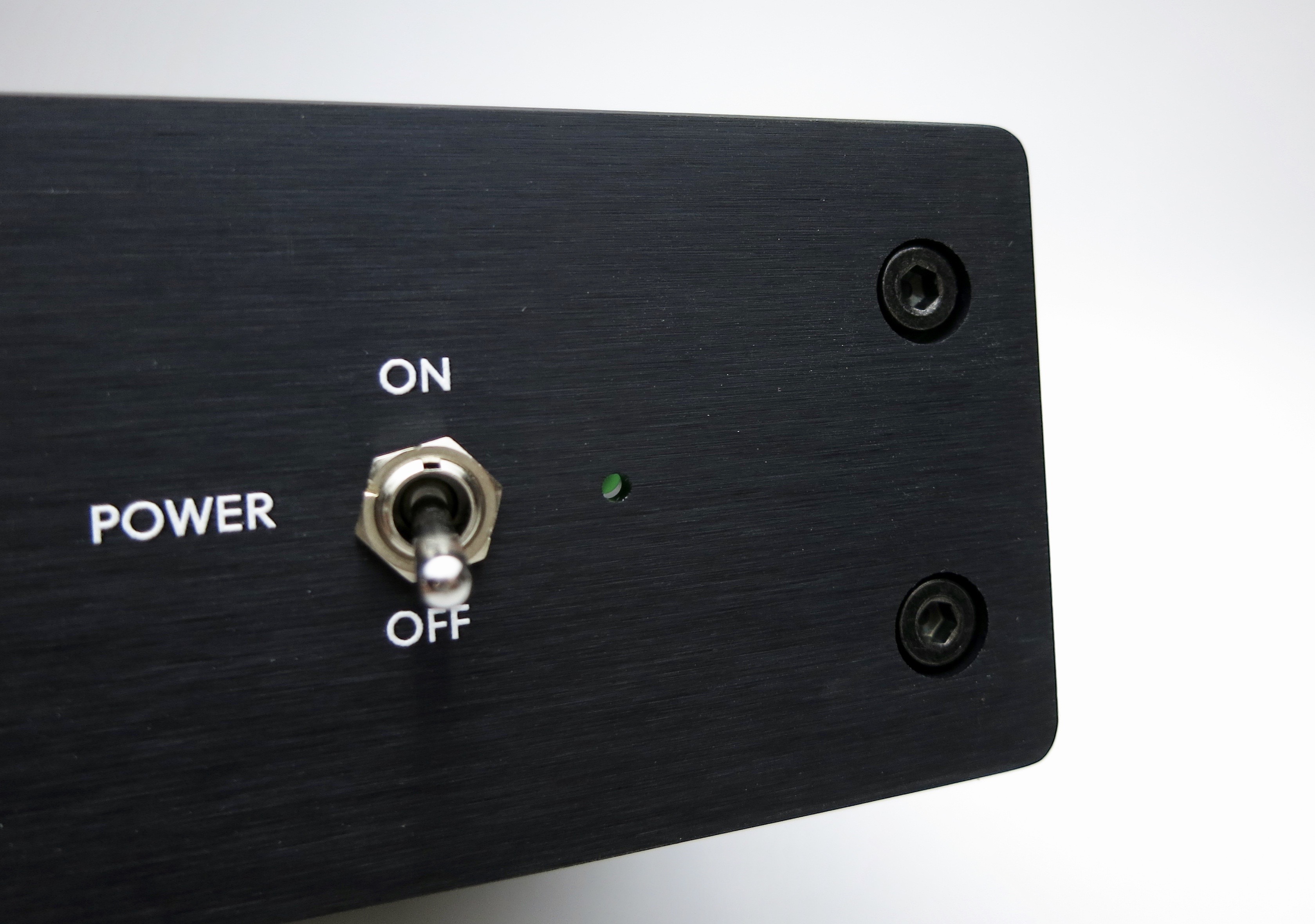
Power switch wiring
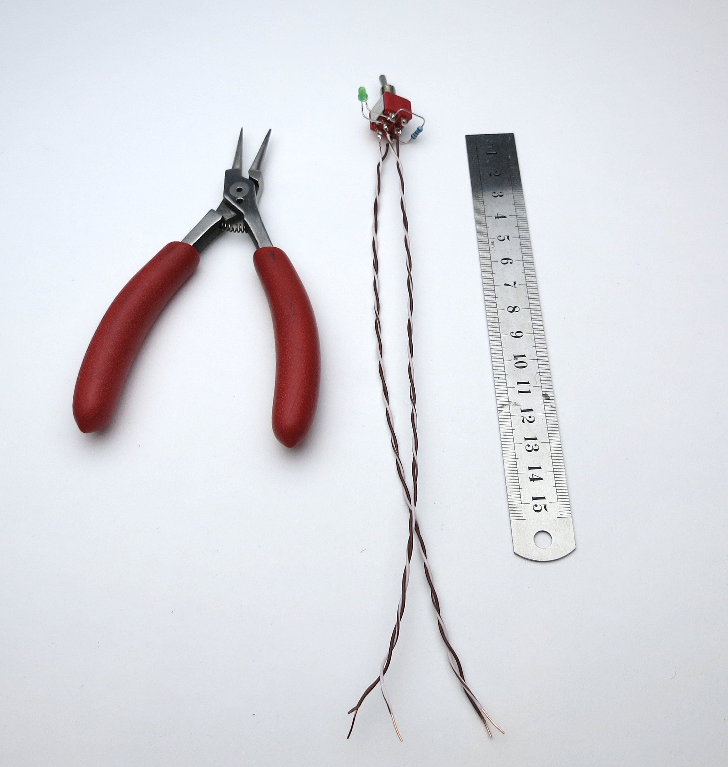
Make the leads long now and trim them to size later.
Begin with the LED
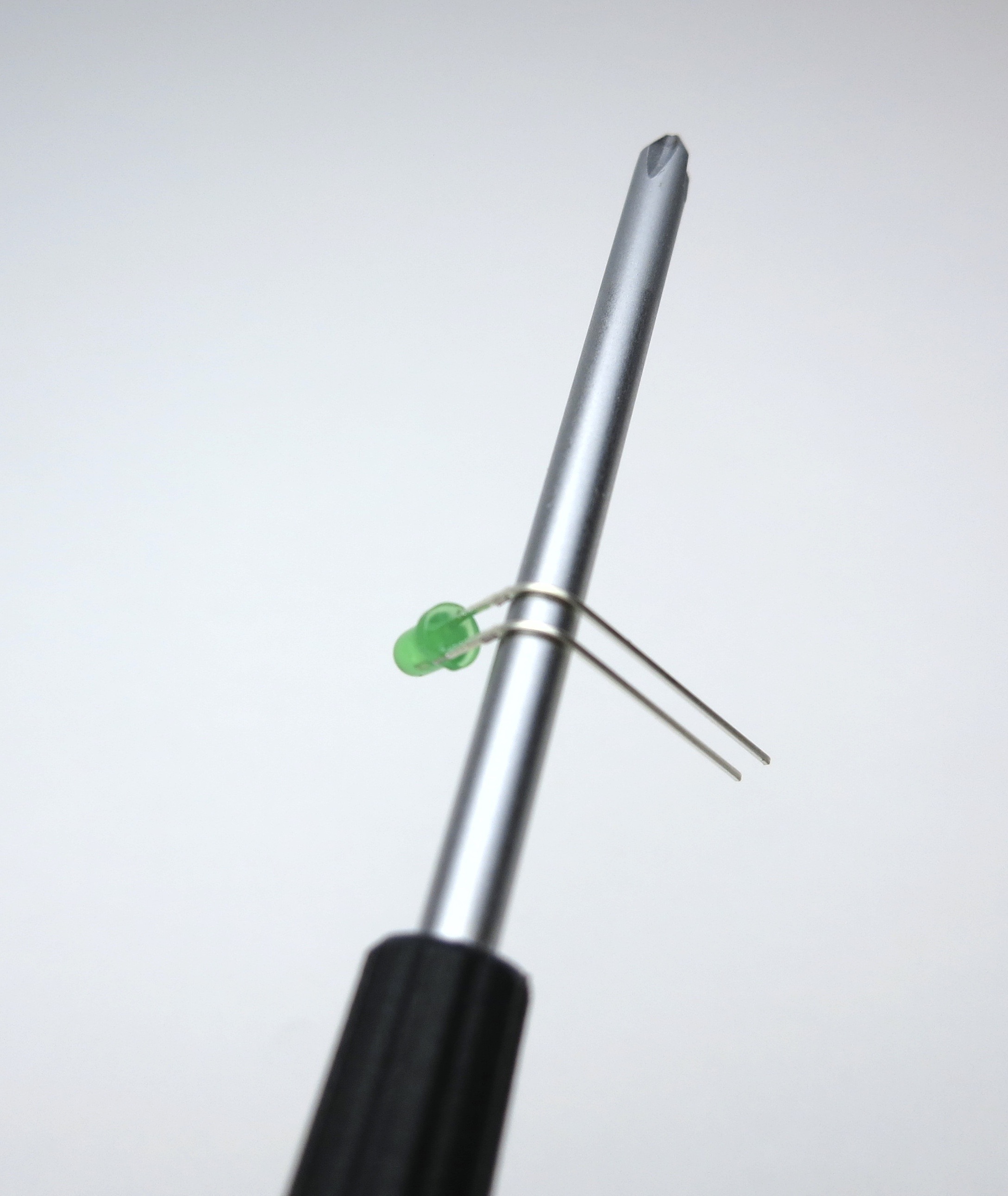
Bend the LED 90deg around the curve of a screwdriver. Long leg on top.
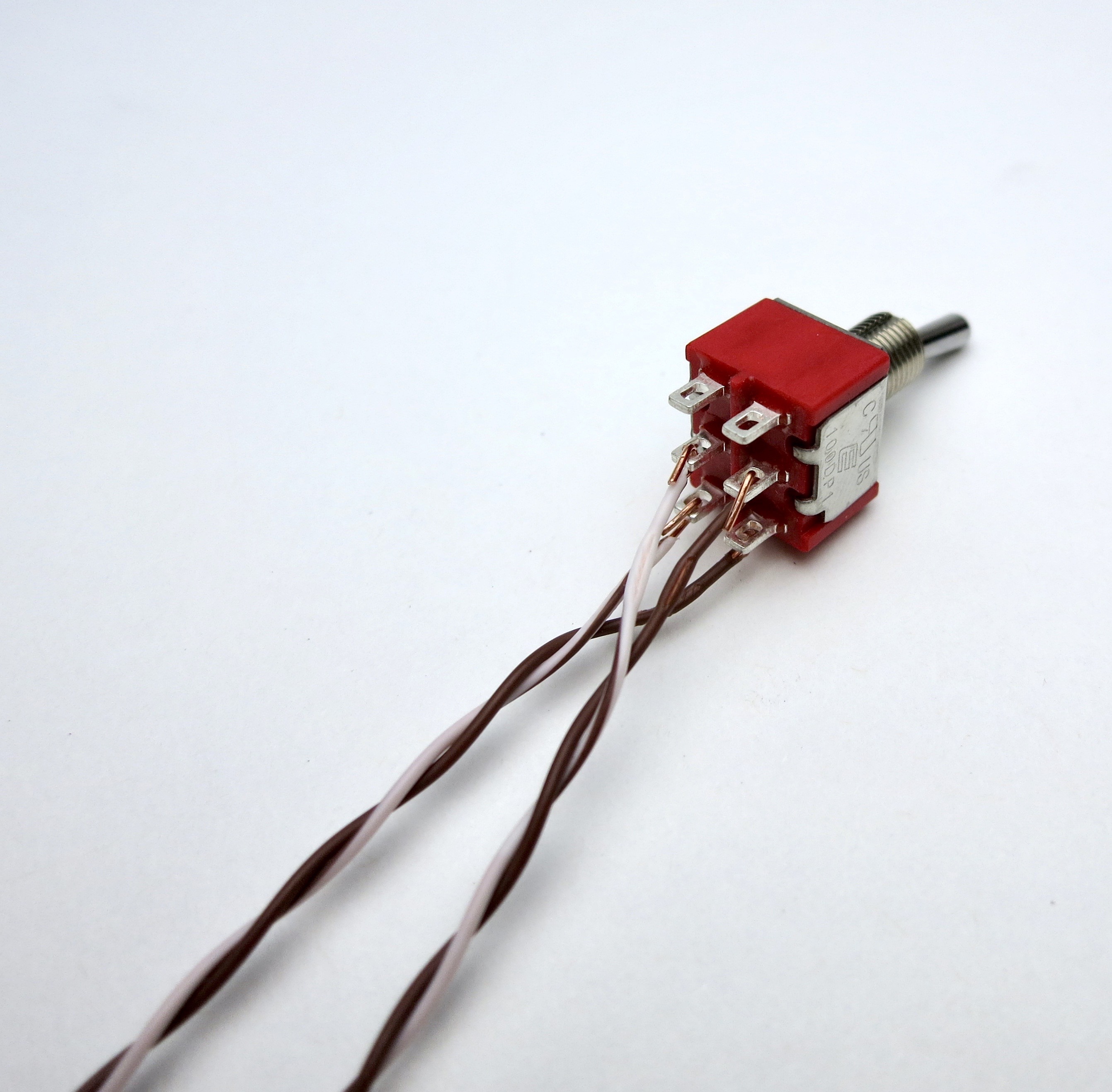
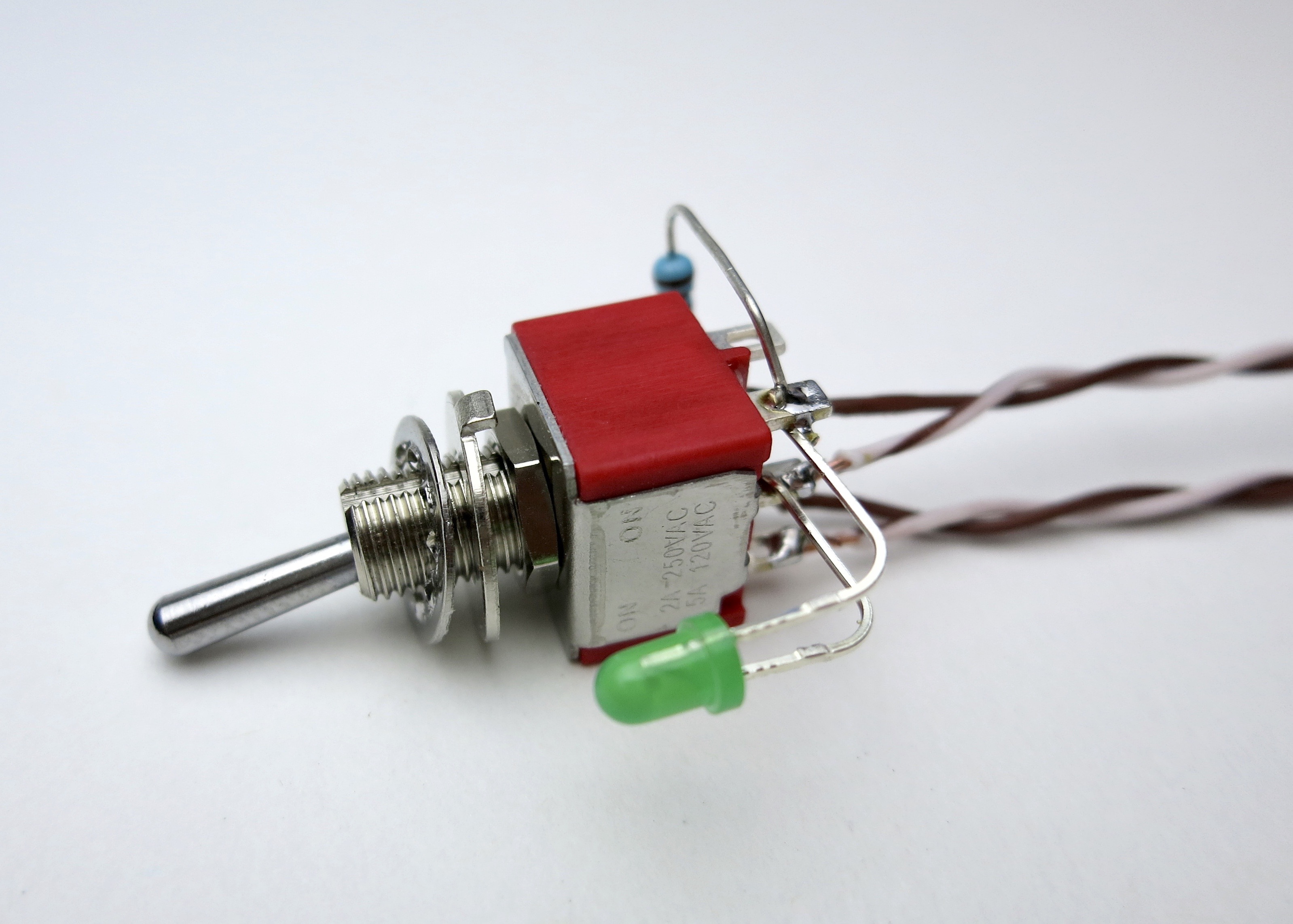
Wires as shown
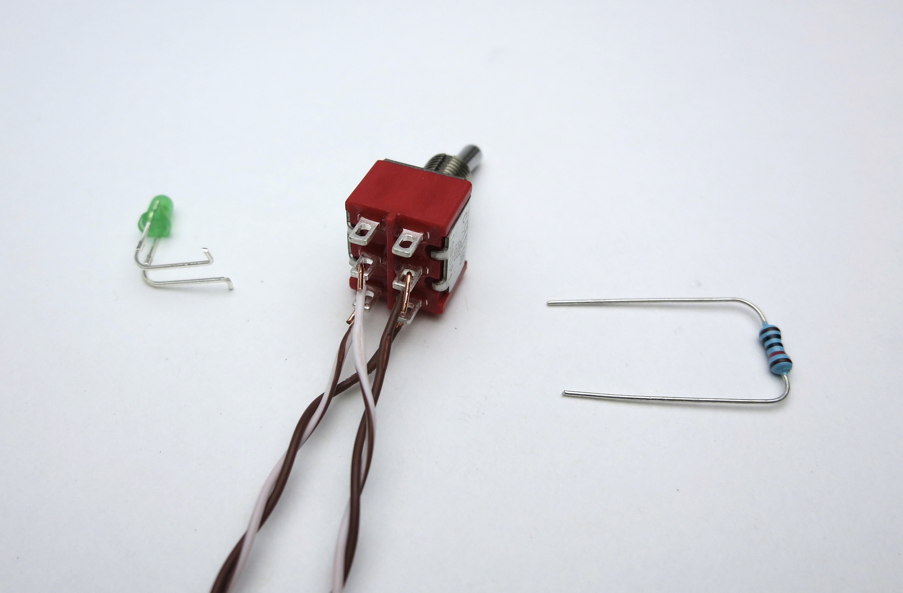
LED and resistor as shown. Making a couple of bends where the LED attaches to the switch will greatly aid assembly.
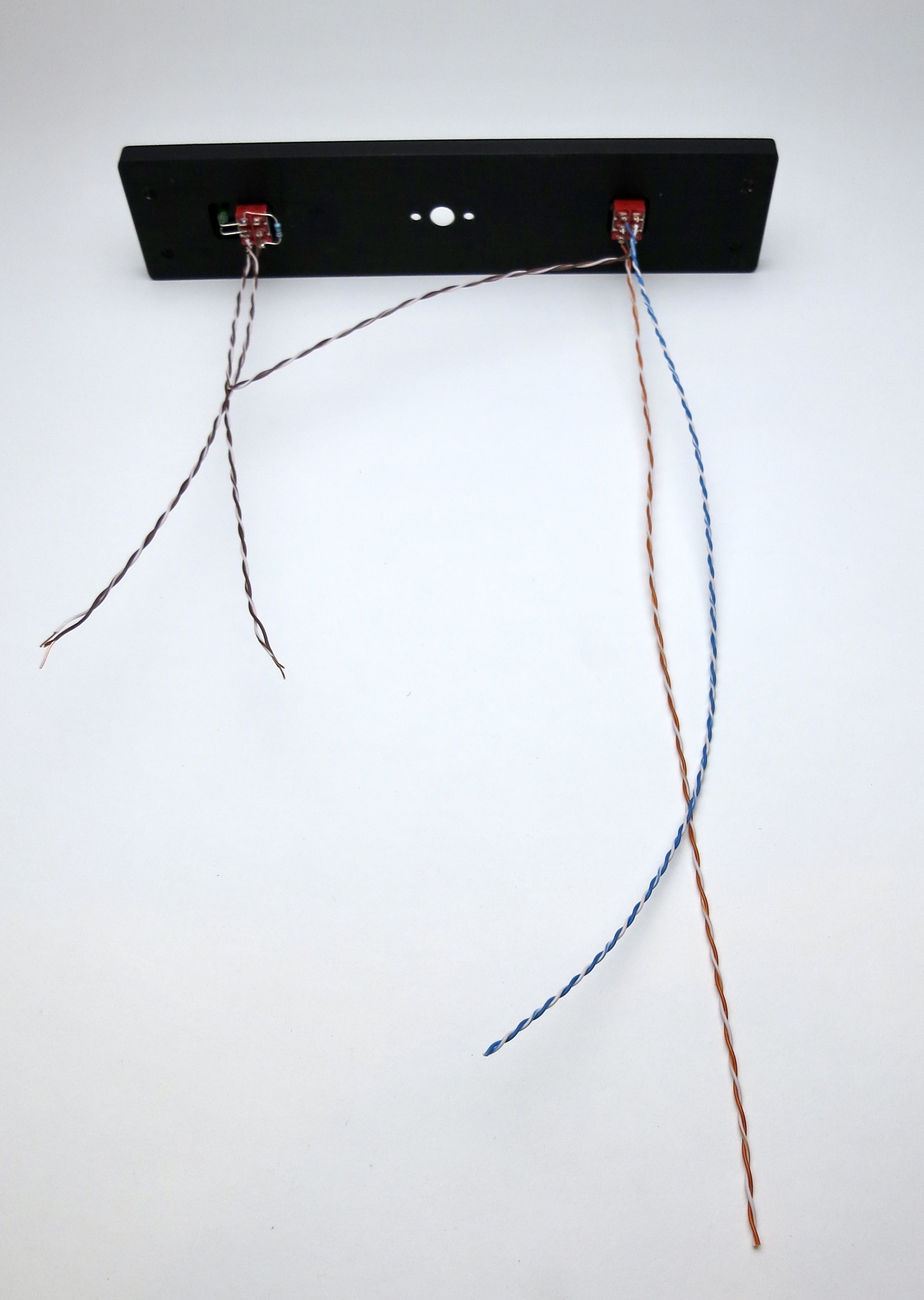
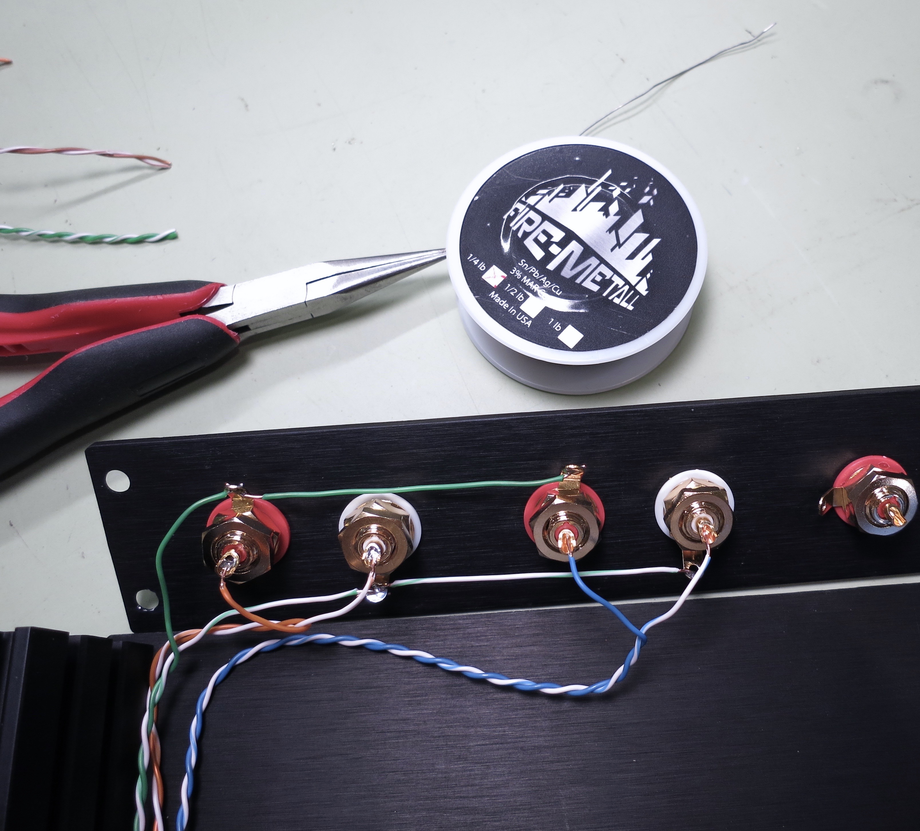
SELECTOR SWITCH WIRING
It's easier to make the wires long now and trim to size when soldering.
Please note that you don't have to follow my color scheme, but if you do checking things will be much easier...
For that matter you can substitute other wire if you like. It's DIY, after all. 😎
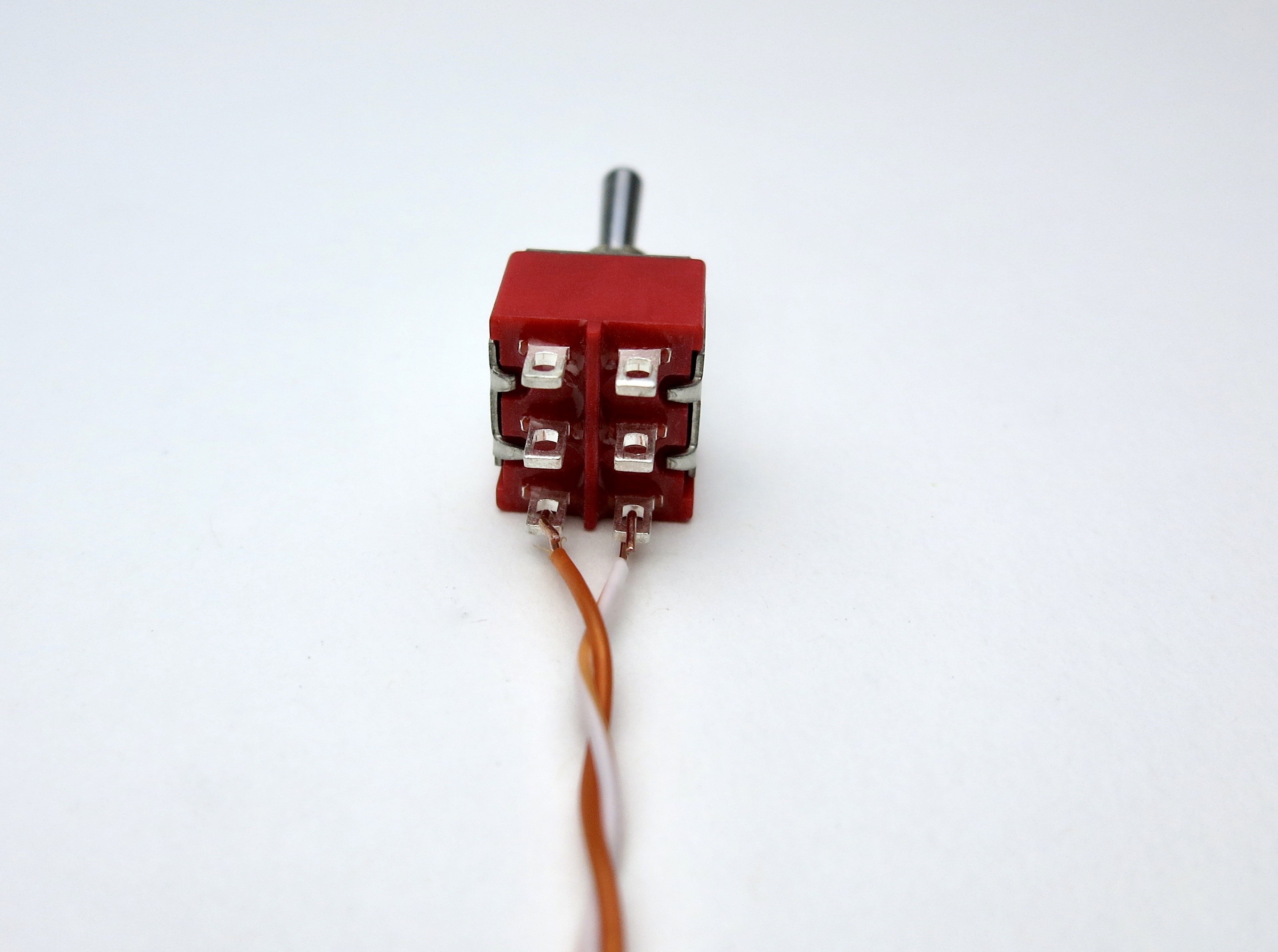
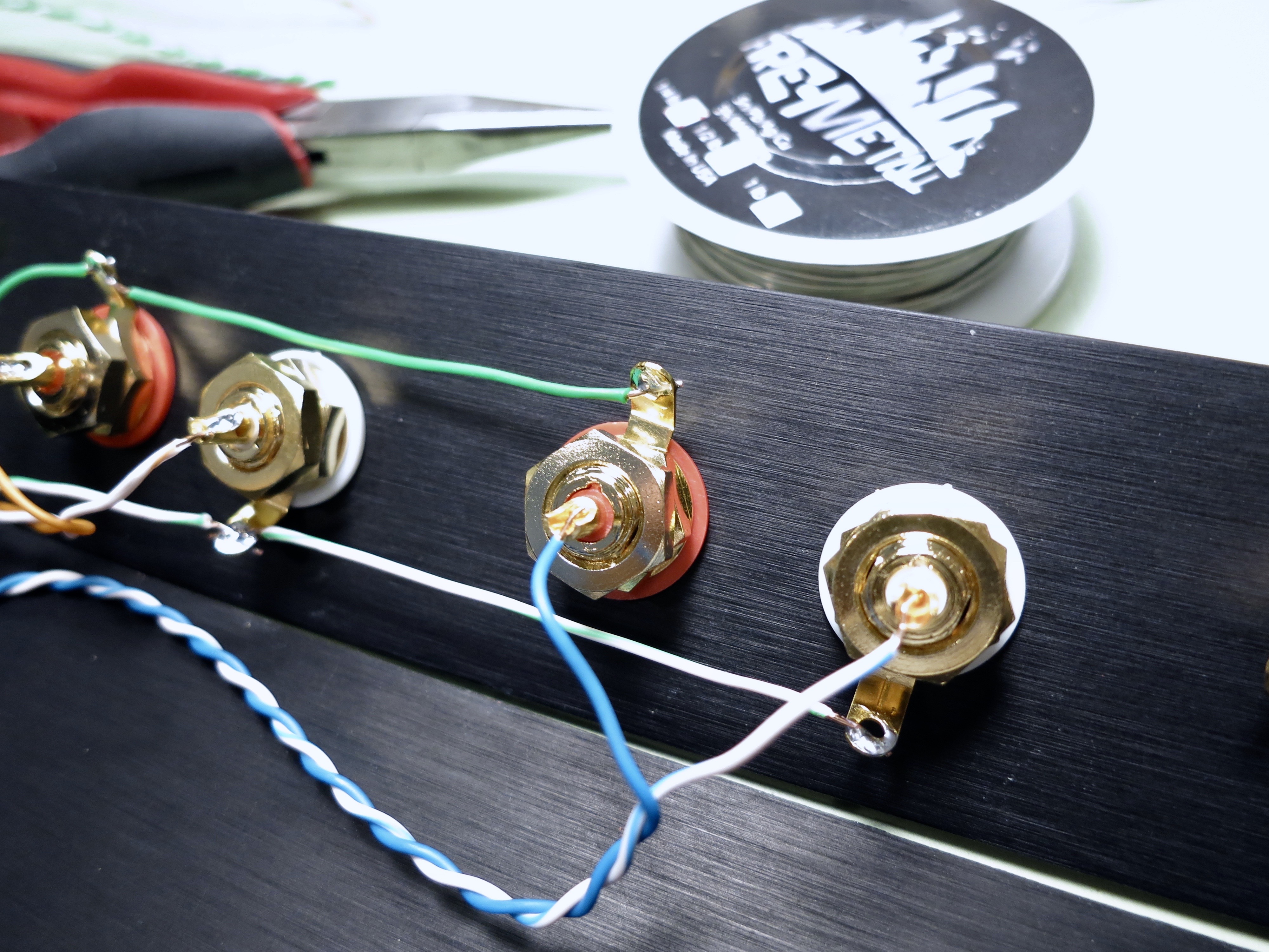
Solid colors on the left, white traces on the right. Begin with orange on the bottom.
Note that there is no "top" or "bottom" to the switch until you attach things to it.
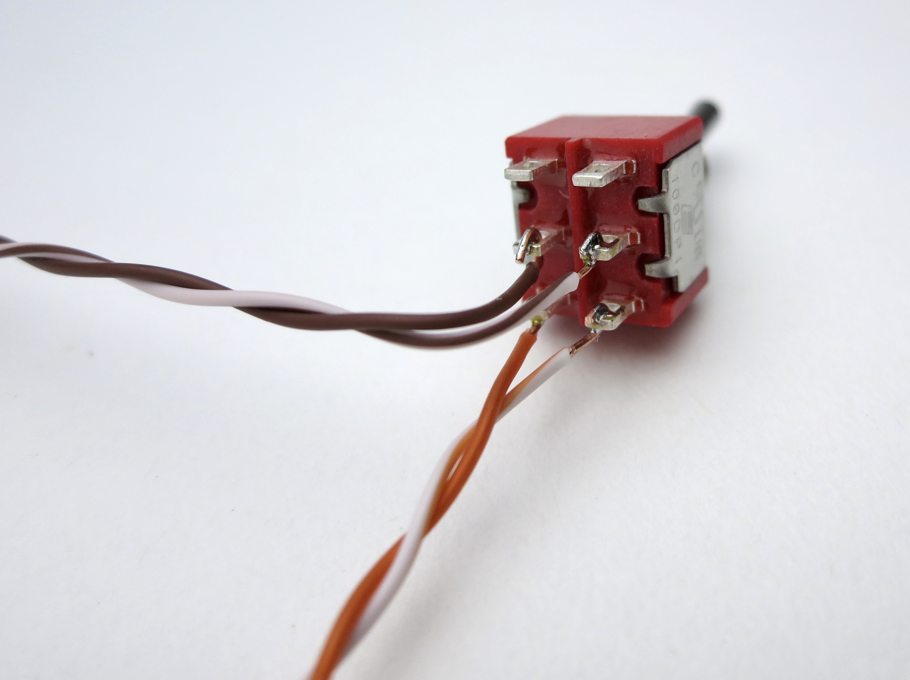
Brown in the middle, this will go to the potentiometer
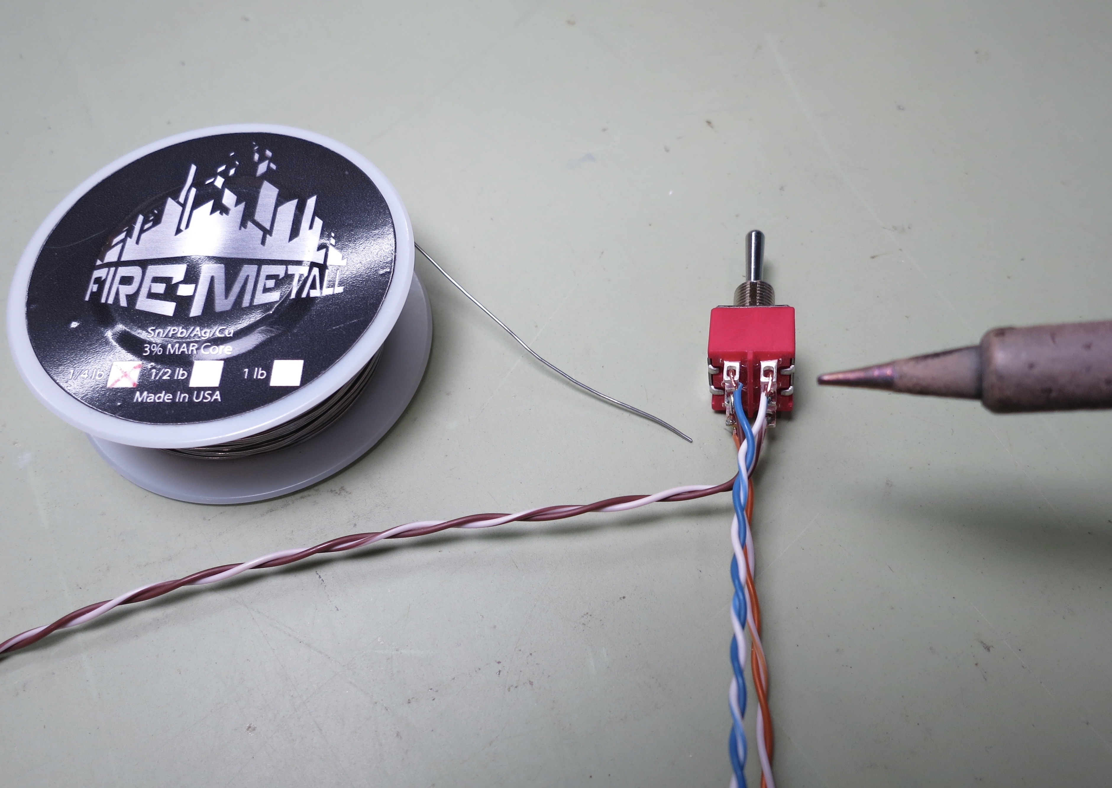
Blue on top.
(Shameless plug: the Fire-Metall solder is absolutely the nicest I have ever used. )
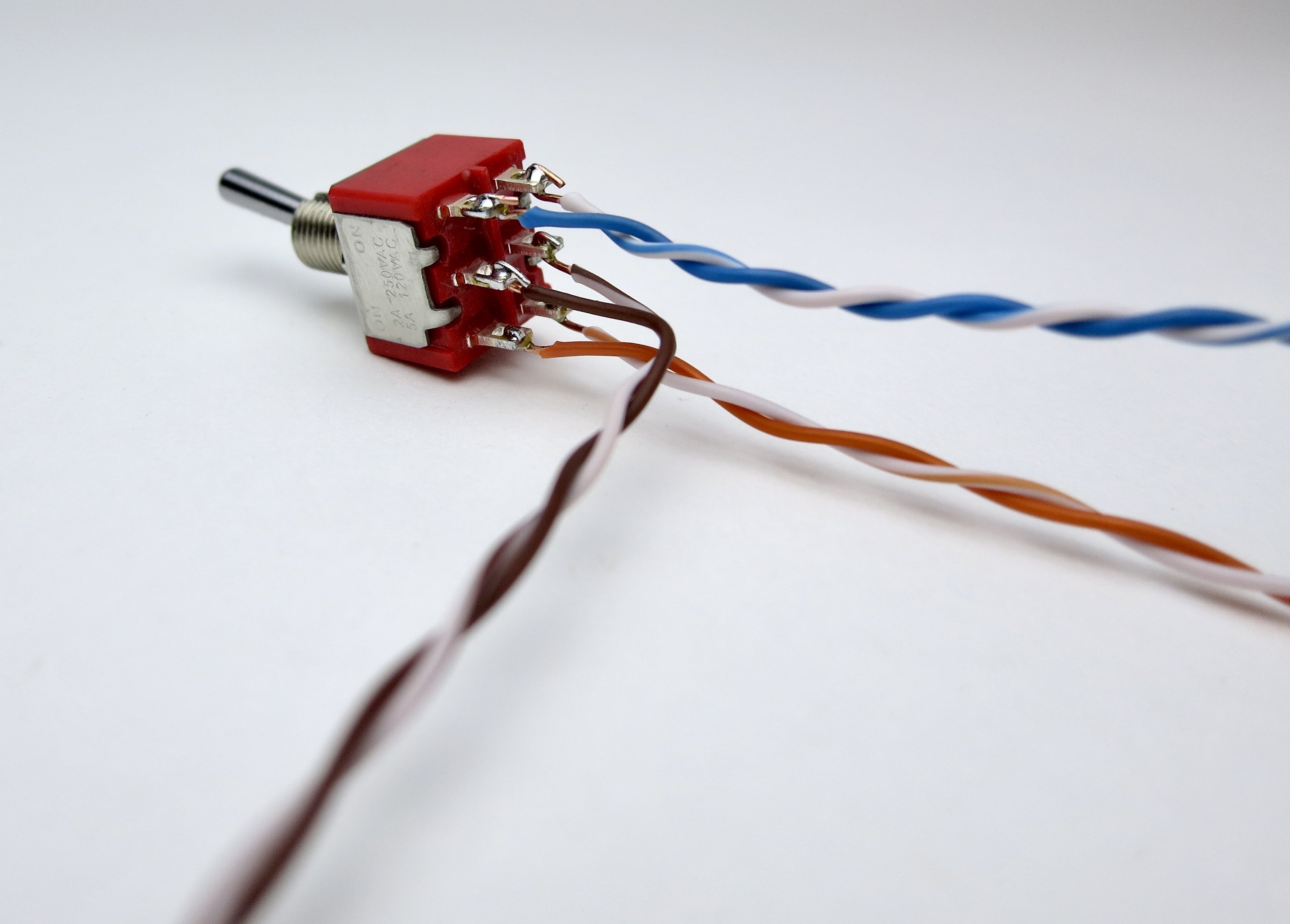
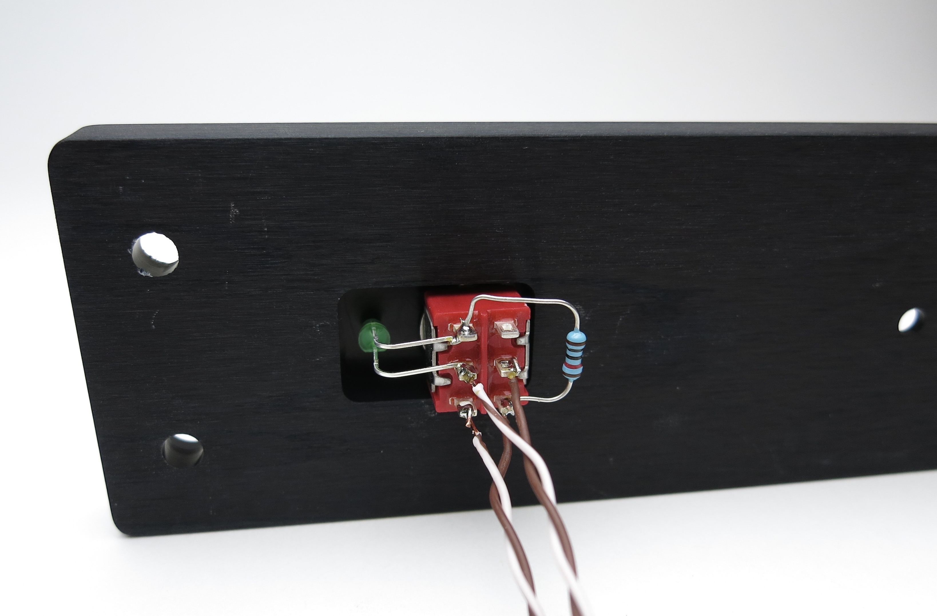
Complete. Mount into front panel as the power switch.
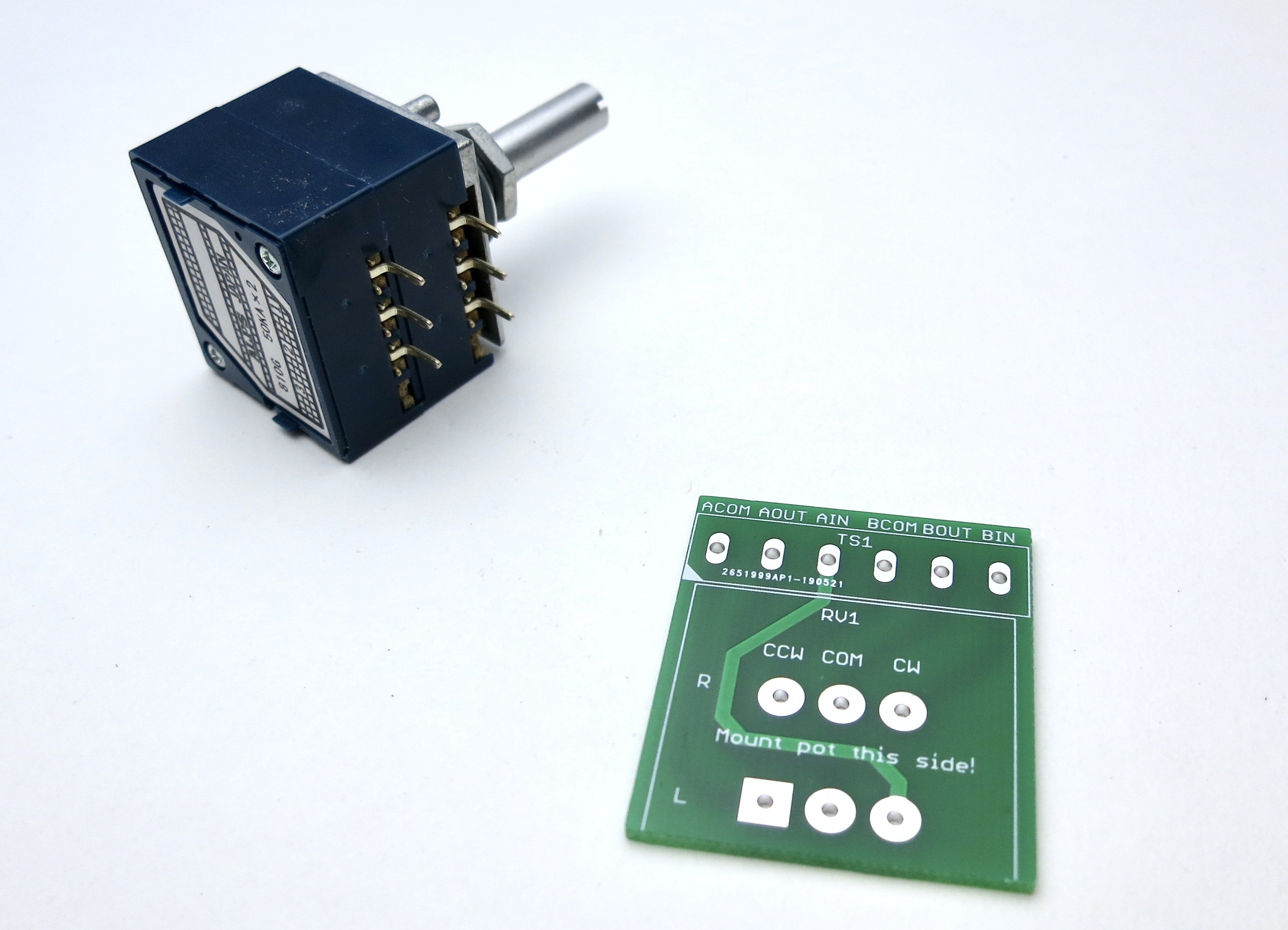
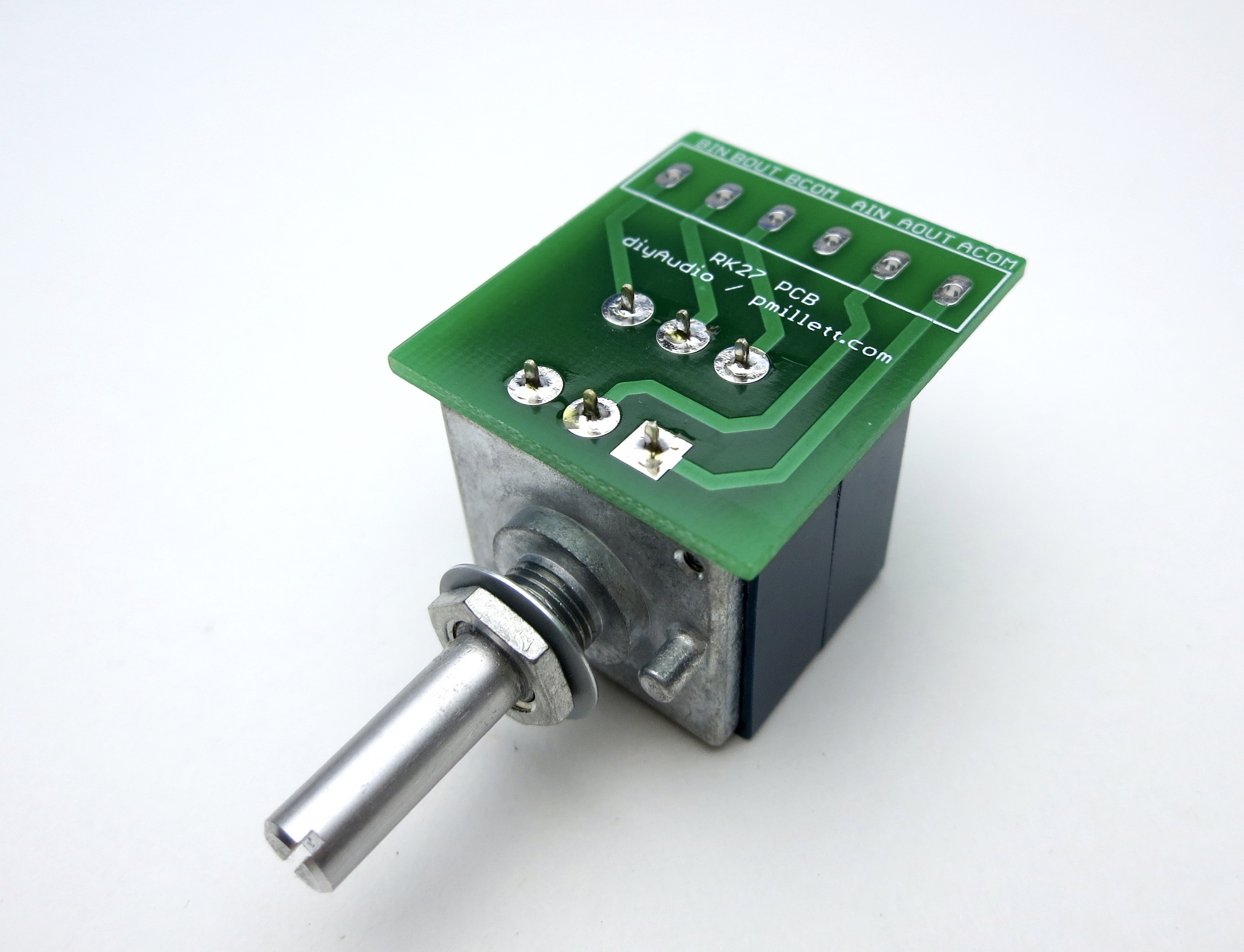
Potentiometer breakout board
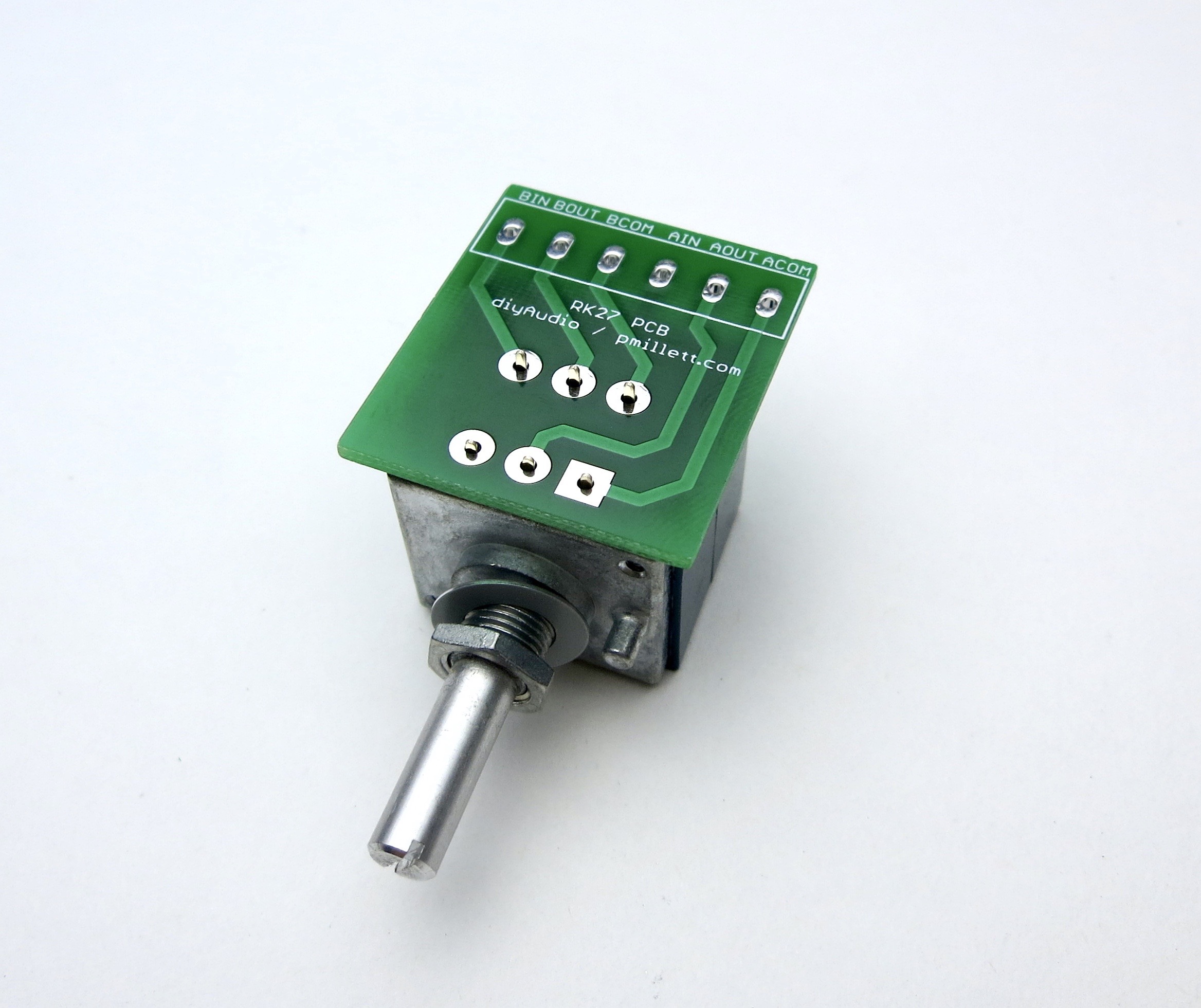
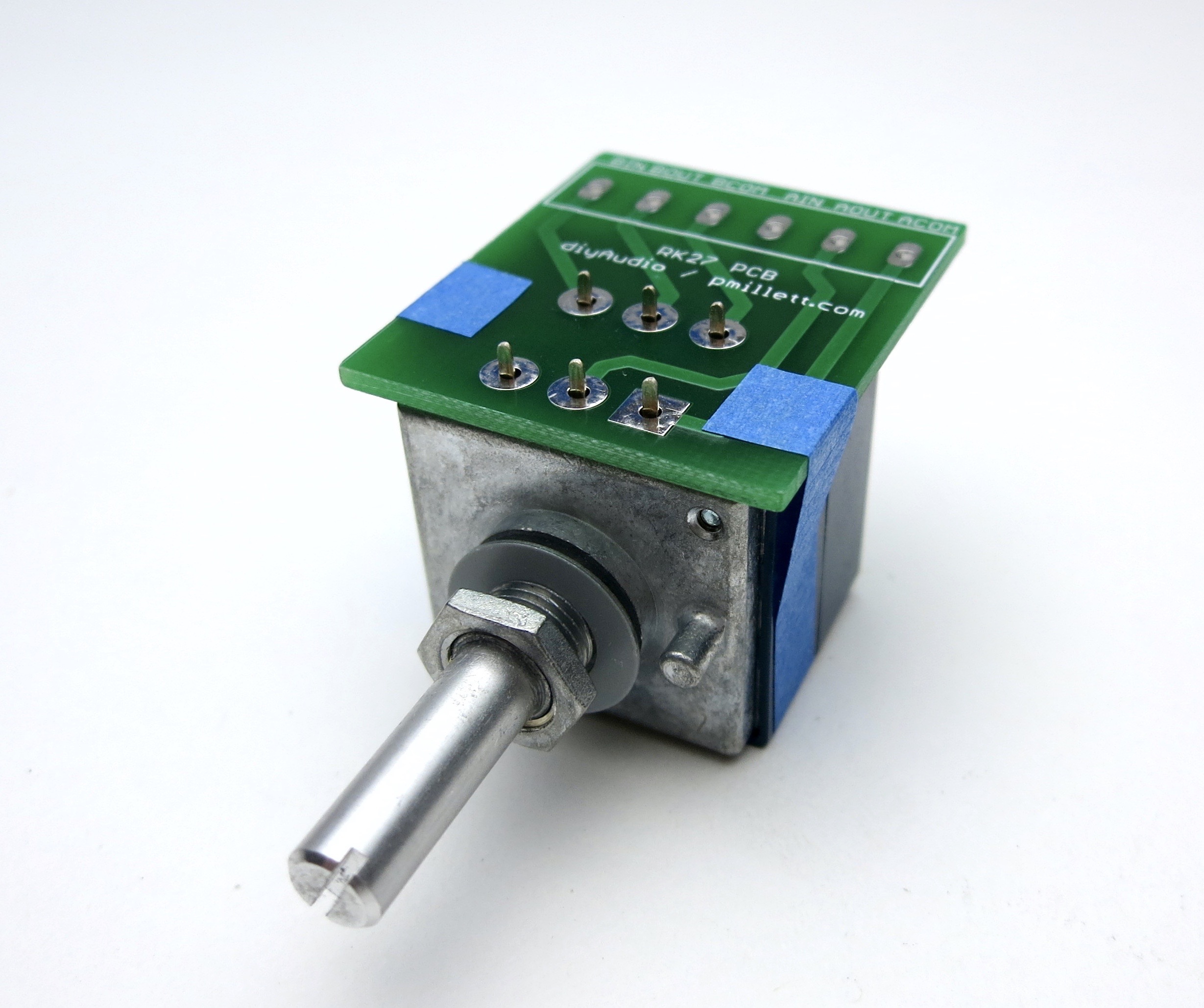
A little tape helps keep everything in place when soldering the PCB
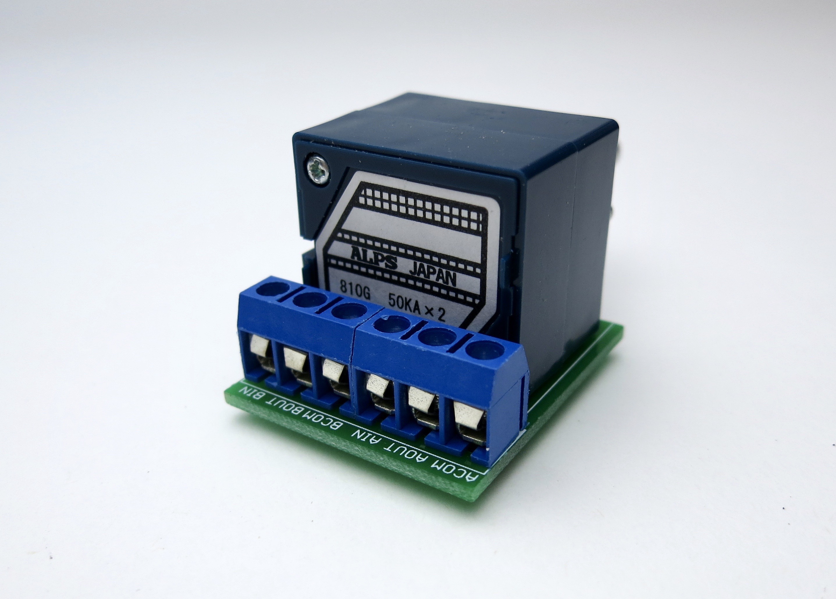
The screw terminals mount as shown if you want to use them.
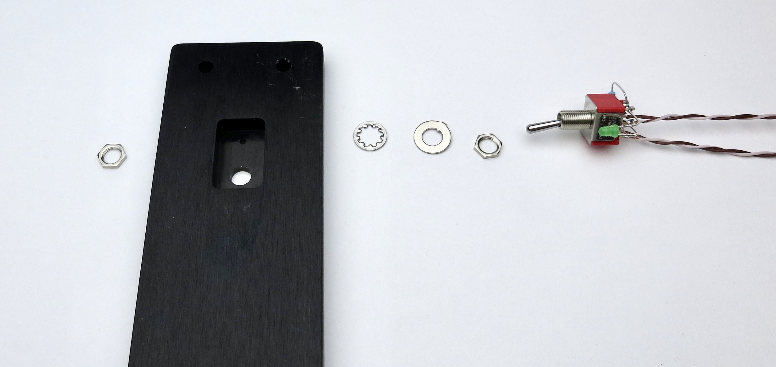
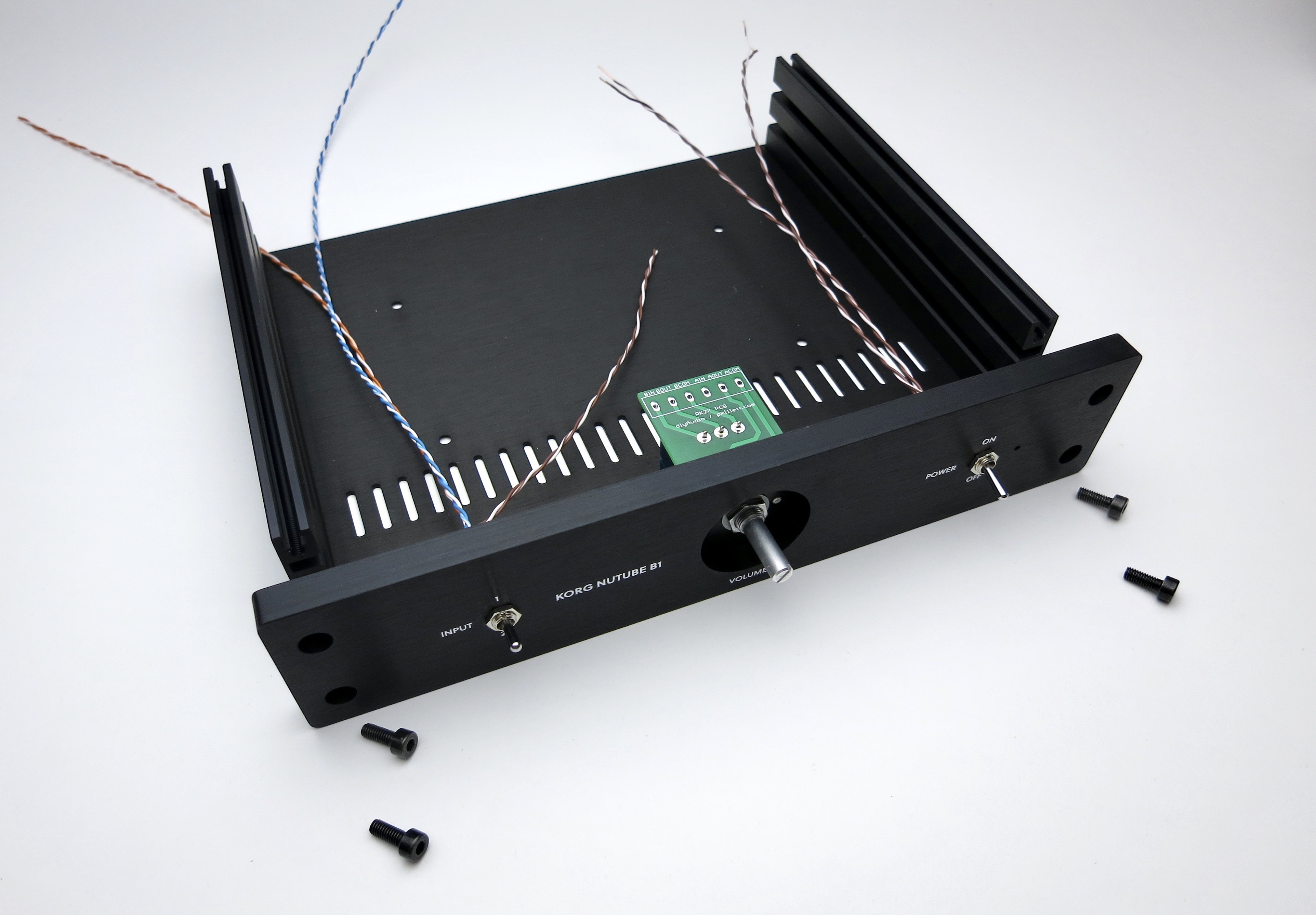
FRONT PANEL MECHANICAL AND WIRING
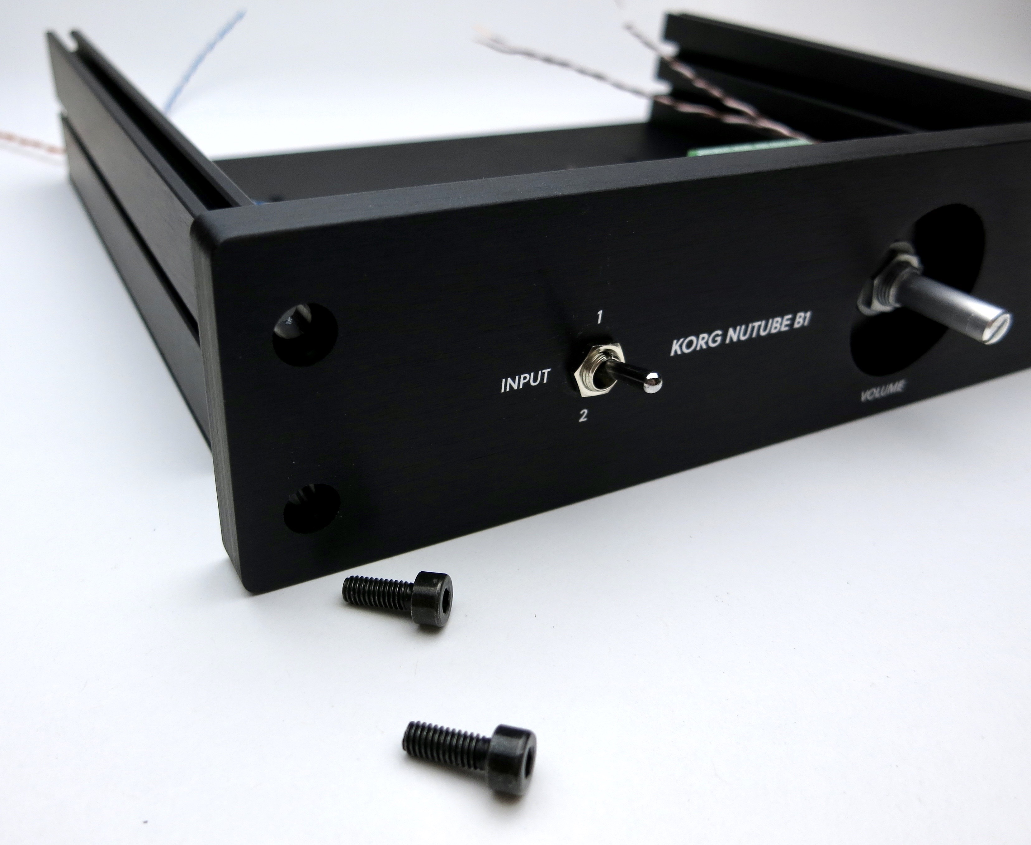
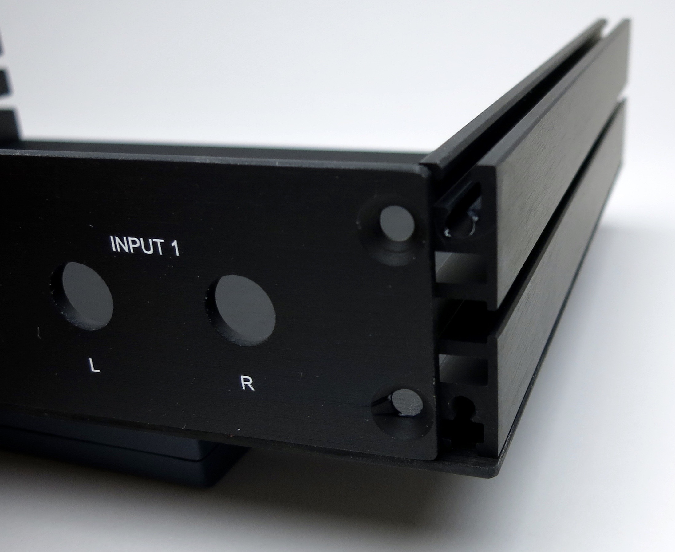
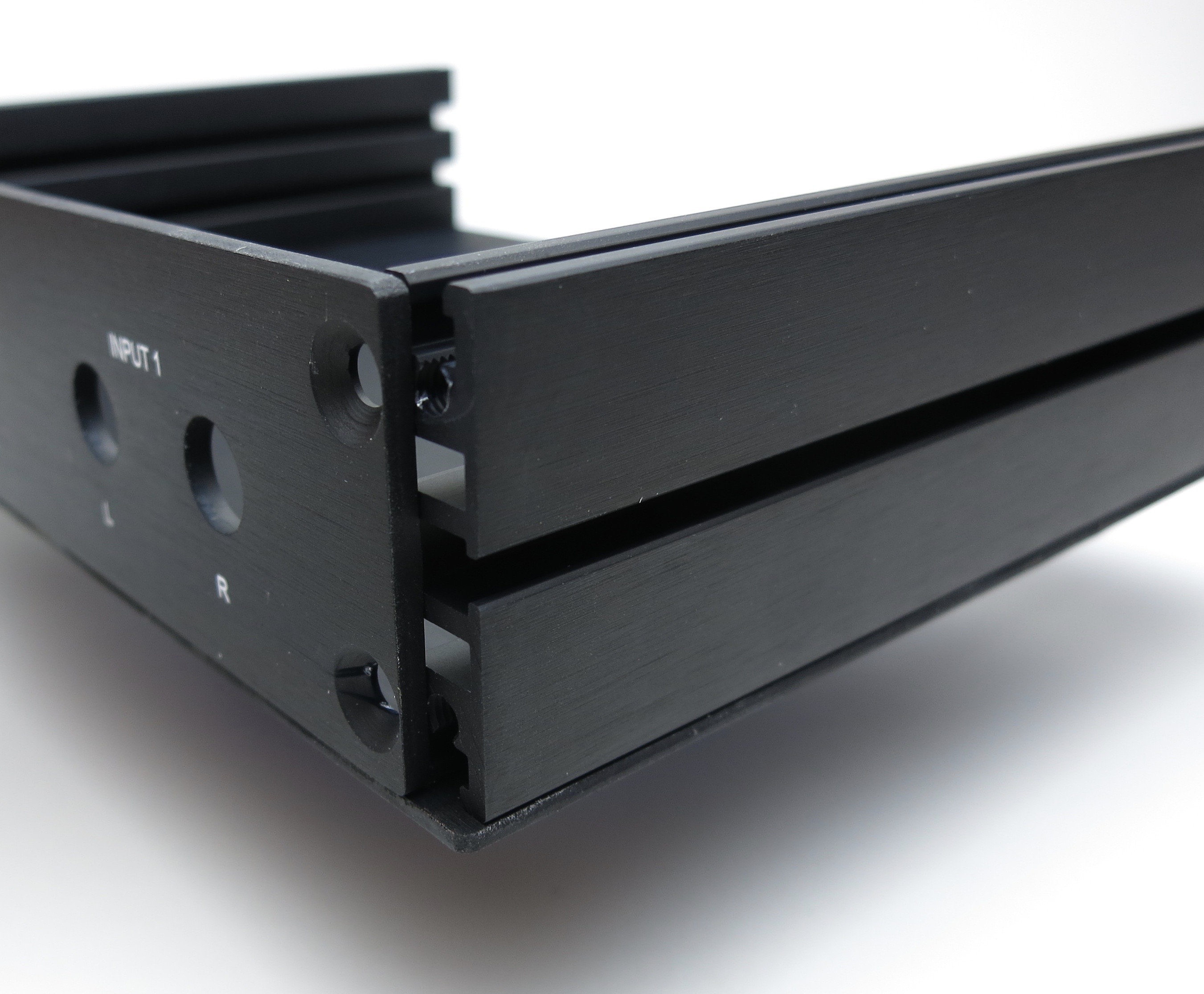
The screws go the threaded section, not the channel where the nuts are.
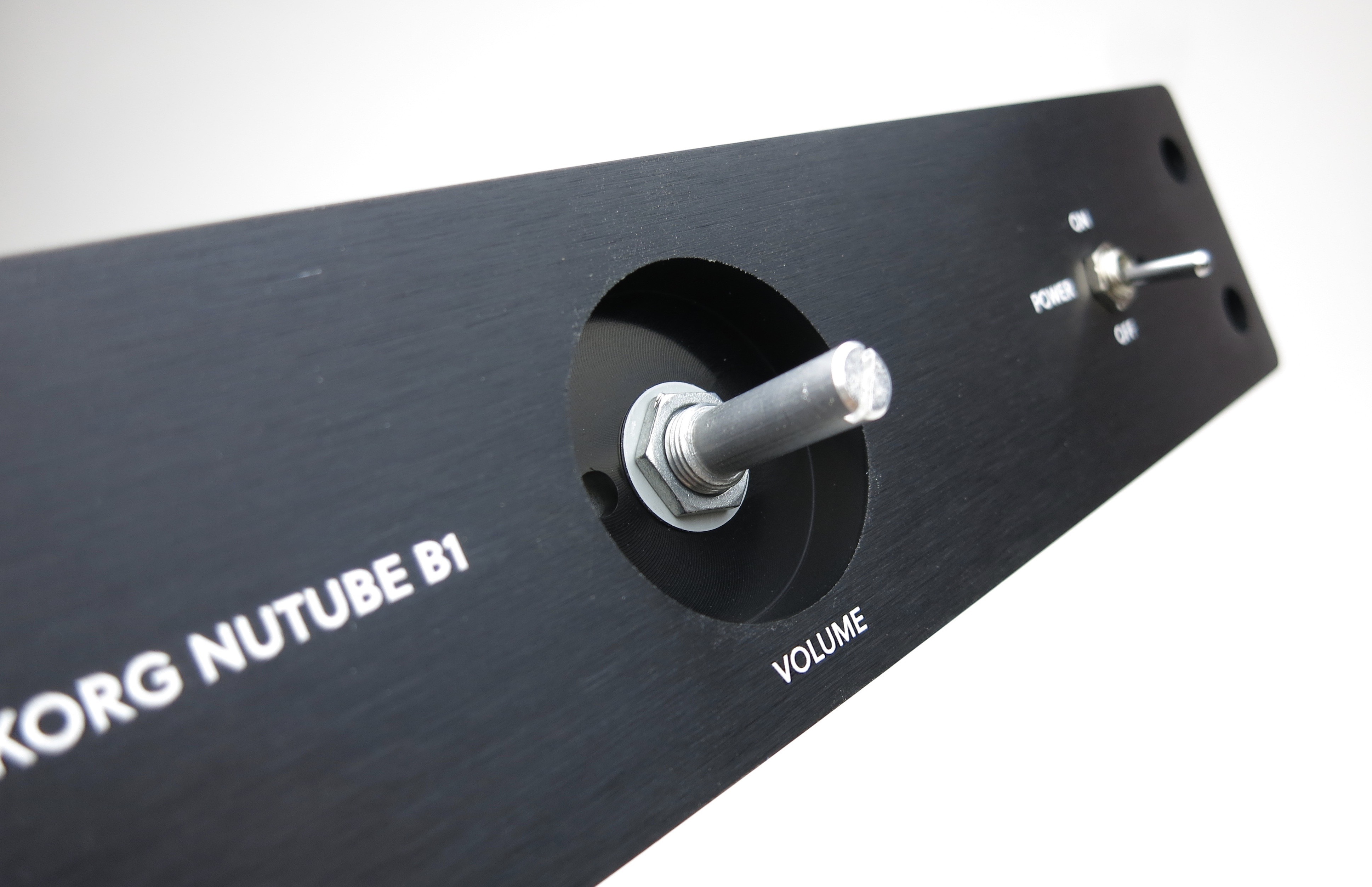
Hopefully you can get your chrome nut on the switches better aligned than this. 😀
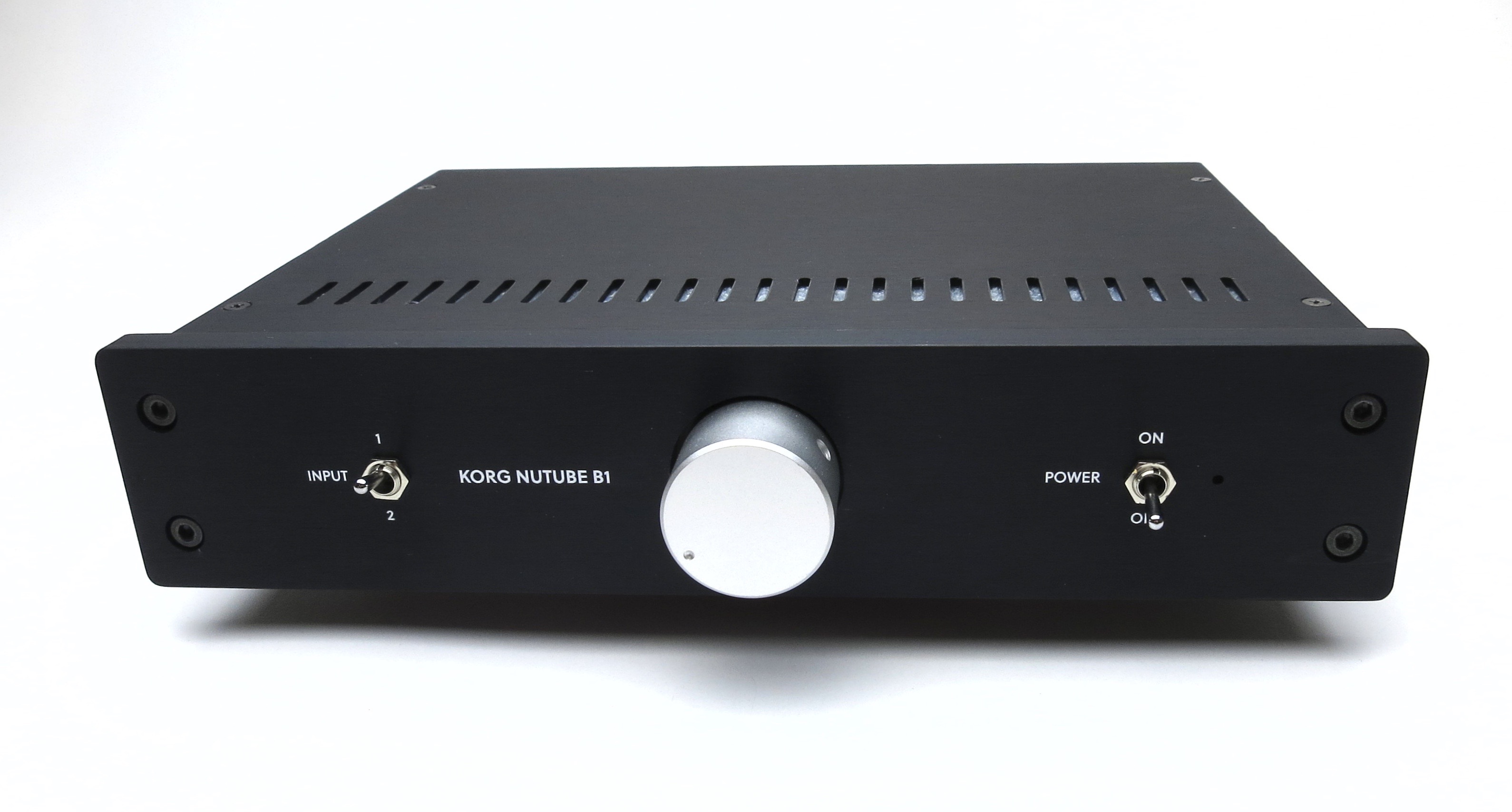
Front panel should look like this now.
Add wiring diagrams
Korg Nutube B1 assembly guide
Nelson Pass' original article - http://www.firstwatt.com/pdf/art_diy_nutube_preamp.pdf
NuTube website - Nutube – English | korgnutube.com – English
Pete Millett's NuTube US website - NuTube
Please read though the entire guide before starting.
If the photos are very big now, reload the page and the forum software should resize them. You can then click into them for proper aspect ratio, and then click into the expand button in the lower left to make them very large.
Neatness counts!! 🙂
CHASSIS MECHANICAL AND WIRING
Gather these parts.
(Well, you don't actually need the knob right now... 🙂 )
Note that the toggle switches are identical.
The bottom panel has the 4 holes drilled for the PCB standoffs
Insert the nuts into the channel
Slide the nuts under the holes then attach the screws
Make sure the holes are aligned with the threaded part of the aluminum extrusion, not the square channel where the nuts go.
Back panel
Barrel jack assembly
RCA assembly
Place the shoulder washer here as shown
Align tabs as shown
Power switch wiring
Make the leads long now and trim them to size later.
Begin with the LED
Bend the LED 90deg around the curve of a screwdriver. Long leg on top.
Wires as shown
LED and resistor as shown. Making a couple of bends where the LED attaches to the switch will greatly aid assembly.
SELECTOR SWITCH WIRING
It's easier to make the wires long now and trim to size when soldering.
Please note that you don't have to follow my color scheme, but if you do checking things will be much easier...
For that matter you can substitute other wire if you like. It's DIY, after all. 😎
Solid colors on the left, white traces on the right. Begin with orange on the bottom.
Note that there is no "top" or "bottom" to the switch until you attach things to it.
Brown in the middle, this will go to the potentiometer
Blue on top.
(Shameless plug: the Fire-Metall solder is absolutely the nicest I have ever used. )
Complete. Mount into front panel as the power switch.
Potentiometer breakout board
A little tape helps keep everything in place when soldering the PCB
The screw terminals mount as shown if you want to use them.
FRONT PANEL MECHANICAL AND WIRING
The screws go the threaded section, not the channel where the nuts are.
Hopefully you can get your chrome nut on the switches better aligned than this. 😀
Front panel should look like this now.
Last edited:
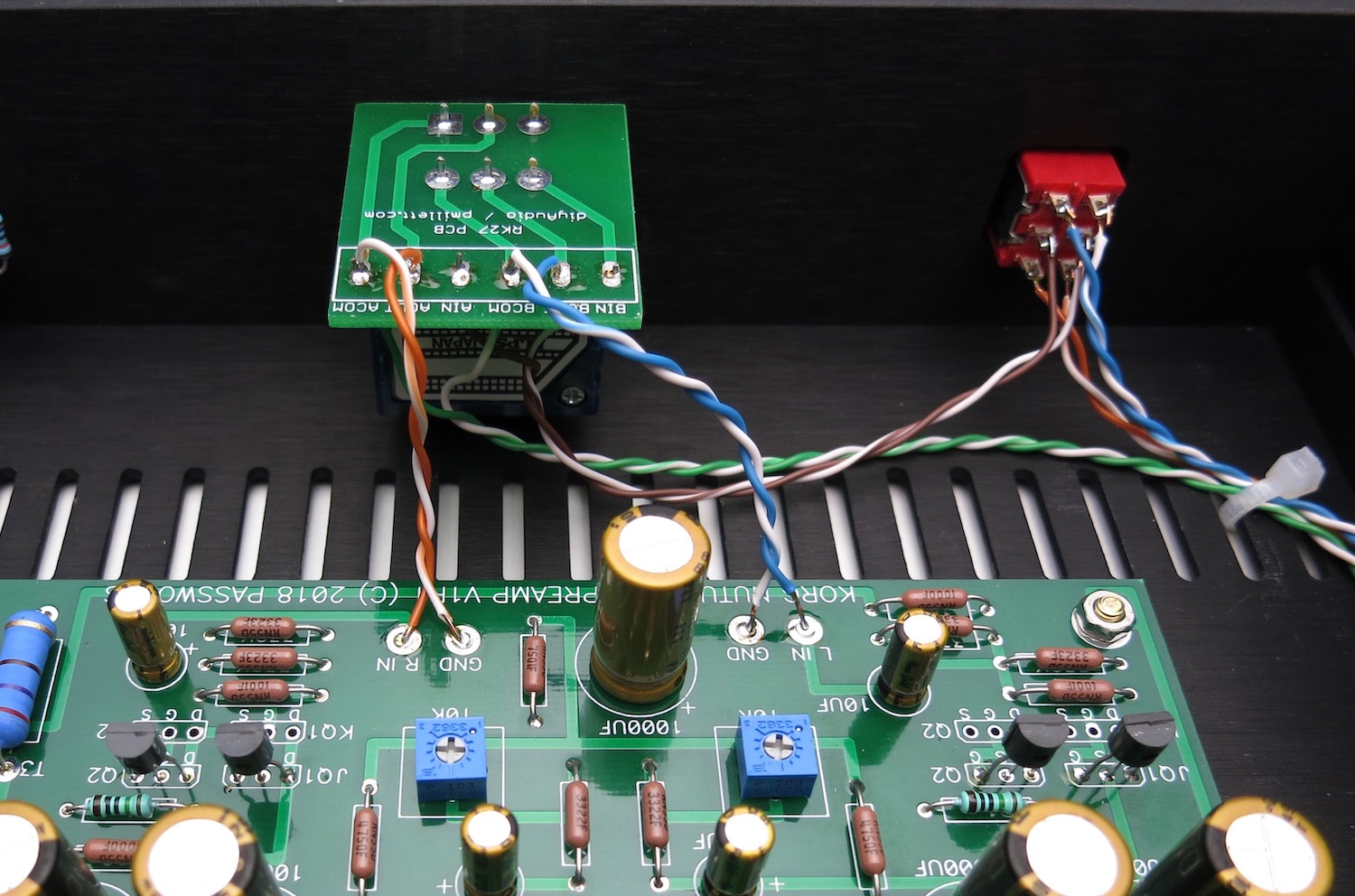
CHASSIS WIRING
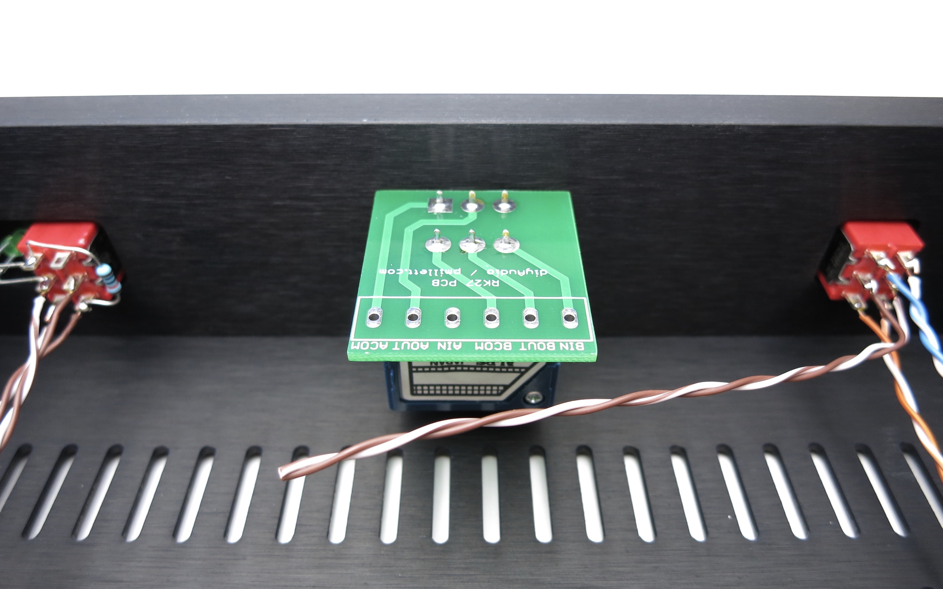
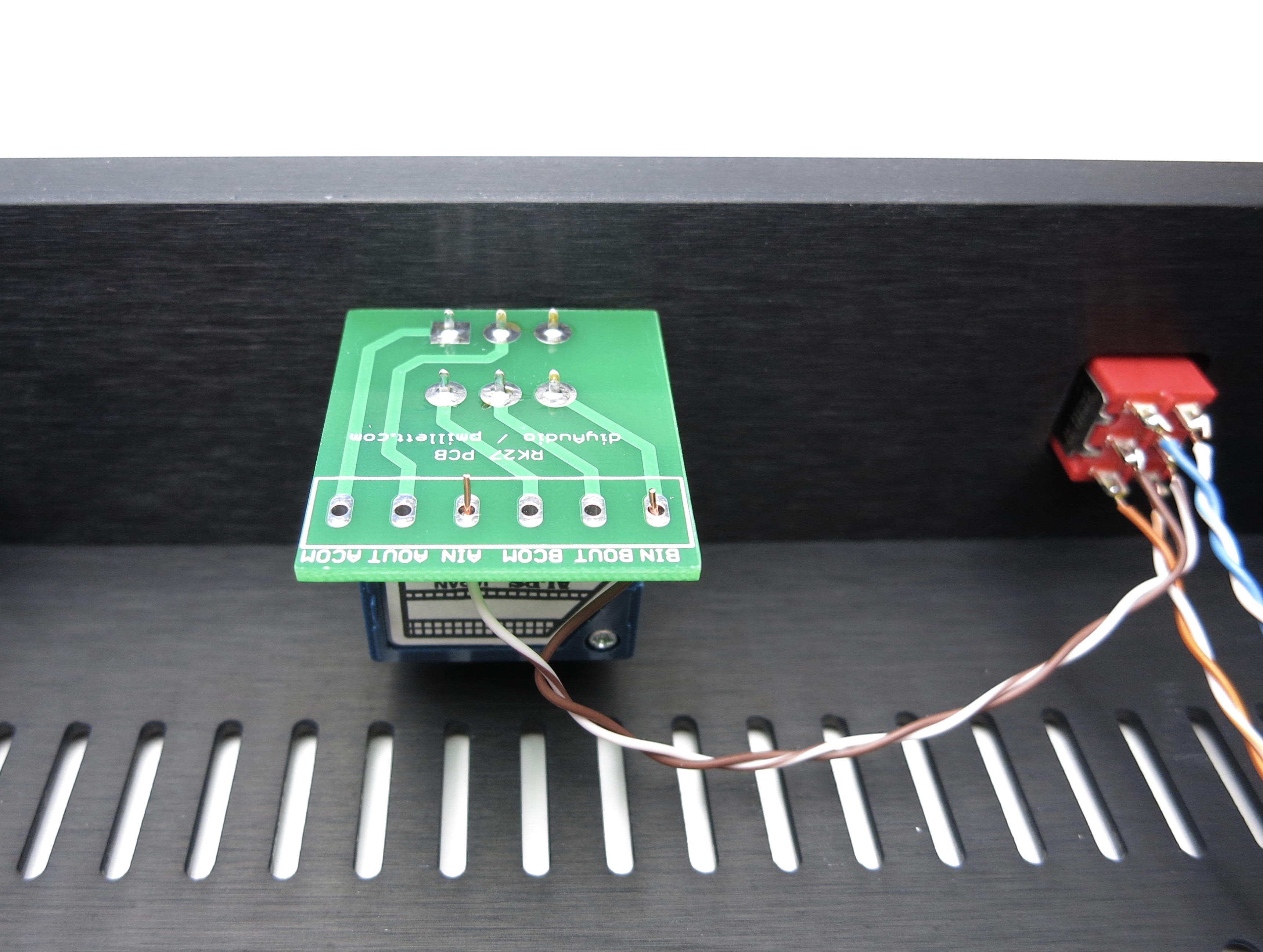
The middle of the switch need to be connected to the IN pads of the pot board. In our wiring scheme so far, solid colors are right and white/trace color are left
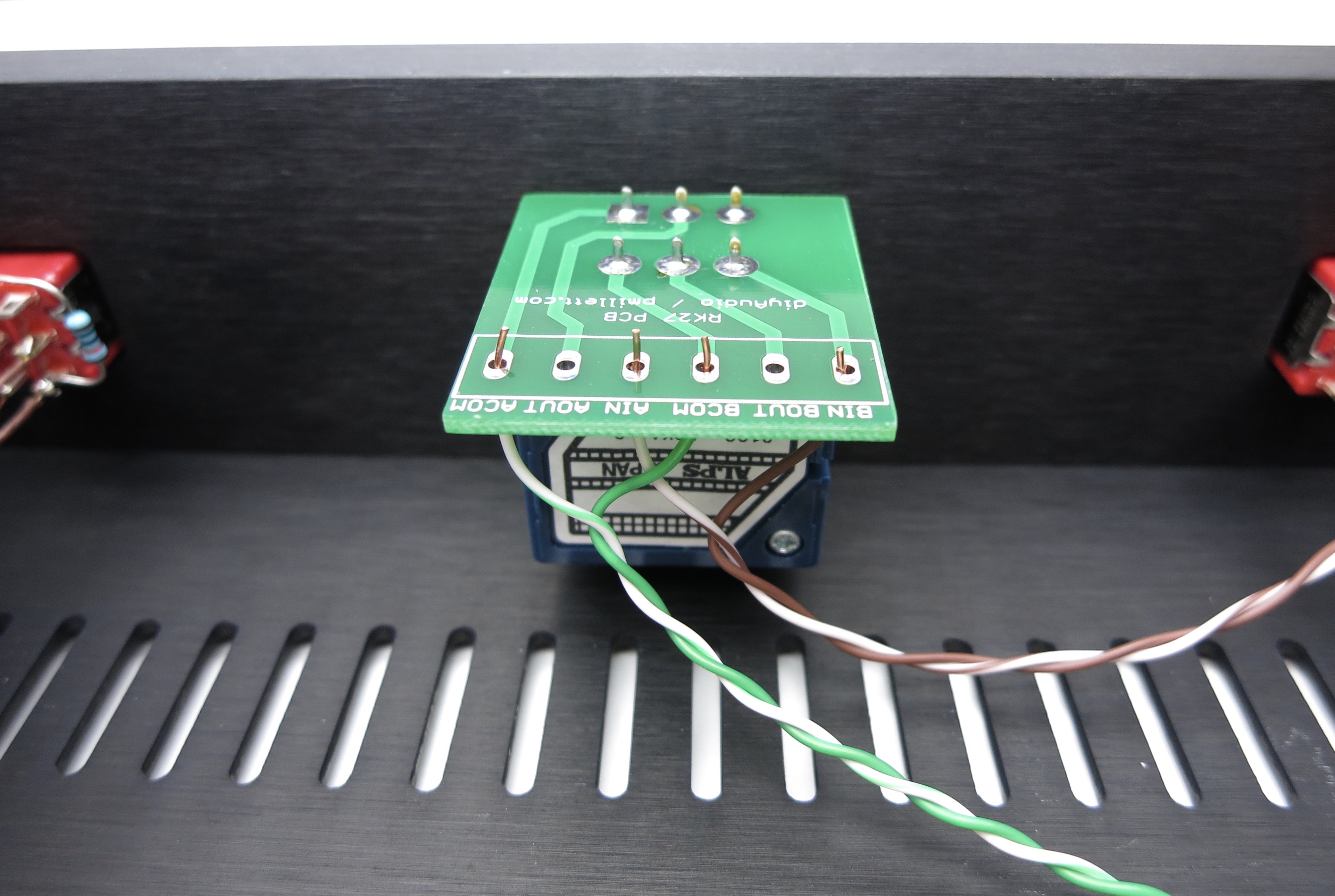
Grounds are connected to the COM pads and go directly to the input RCAs, not connecting to the switch. Solid green is right, white/green left.
Do not solder yet!
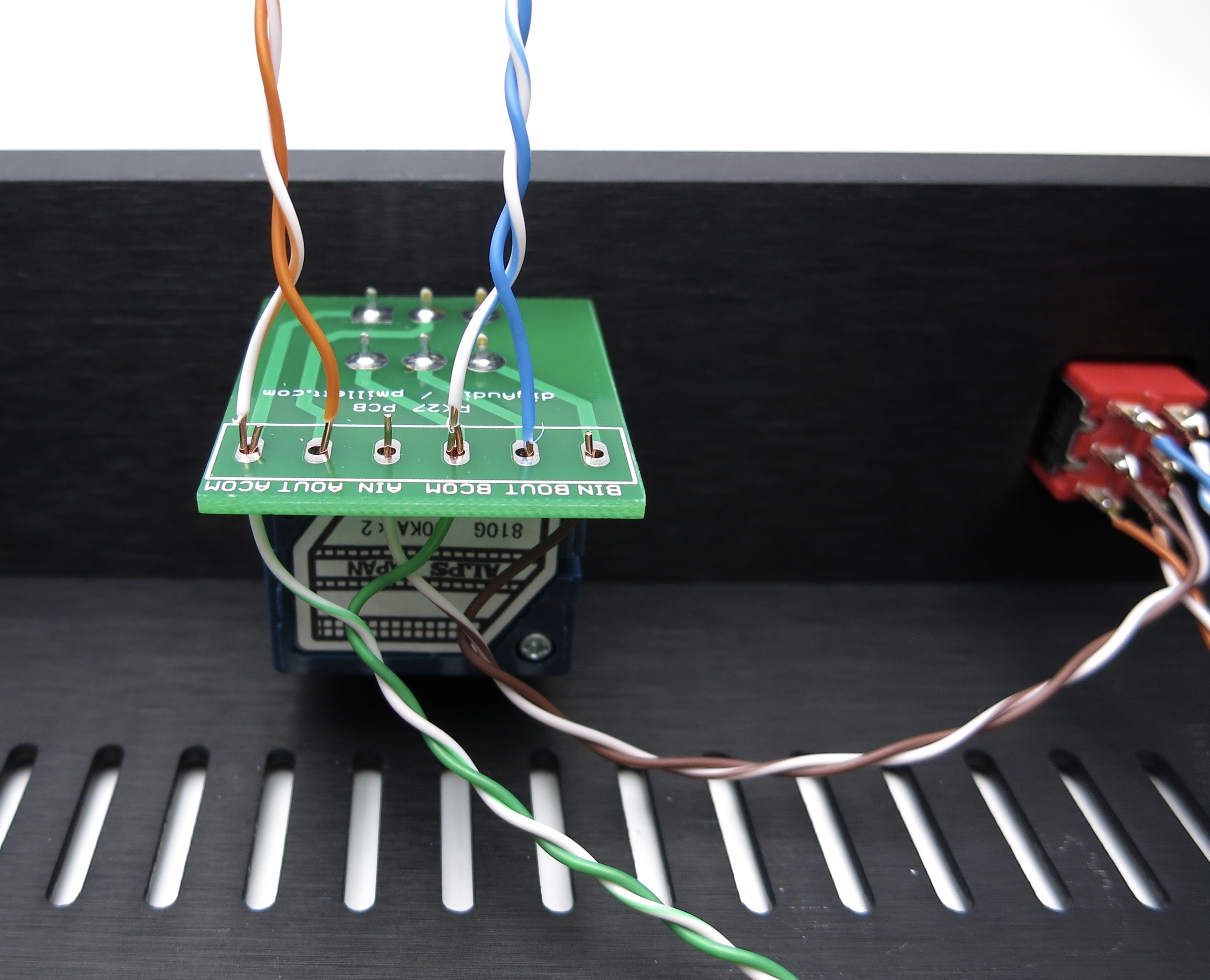
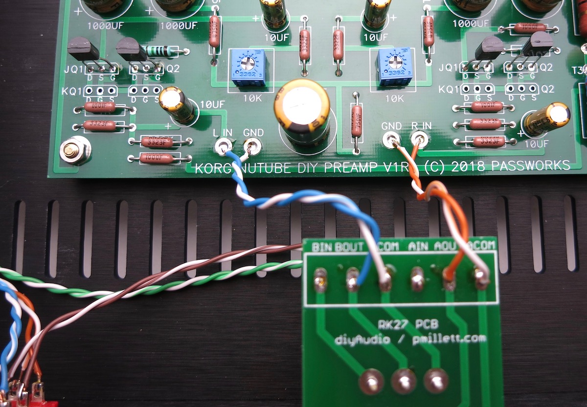
Color coding is changing, sorry... Orange for right (because it's closer ro red) and Blue for left.
Positive is solid, white/trace GND
Solids to OUT, whites to COM
Solder all 6 positions now
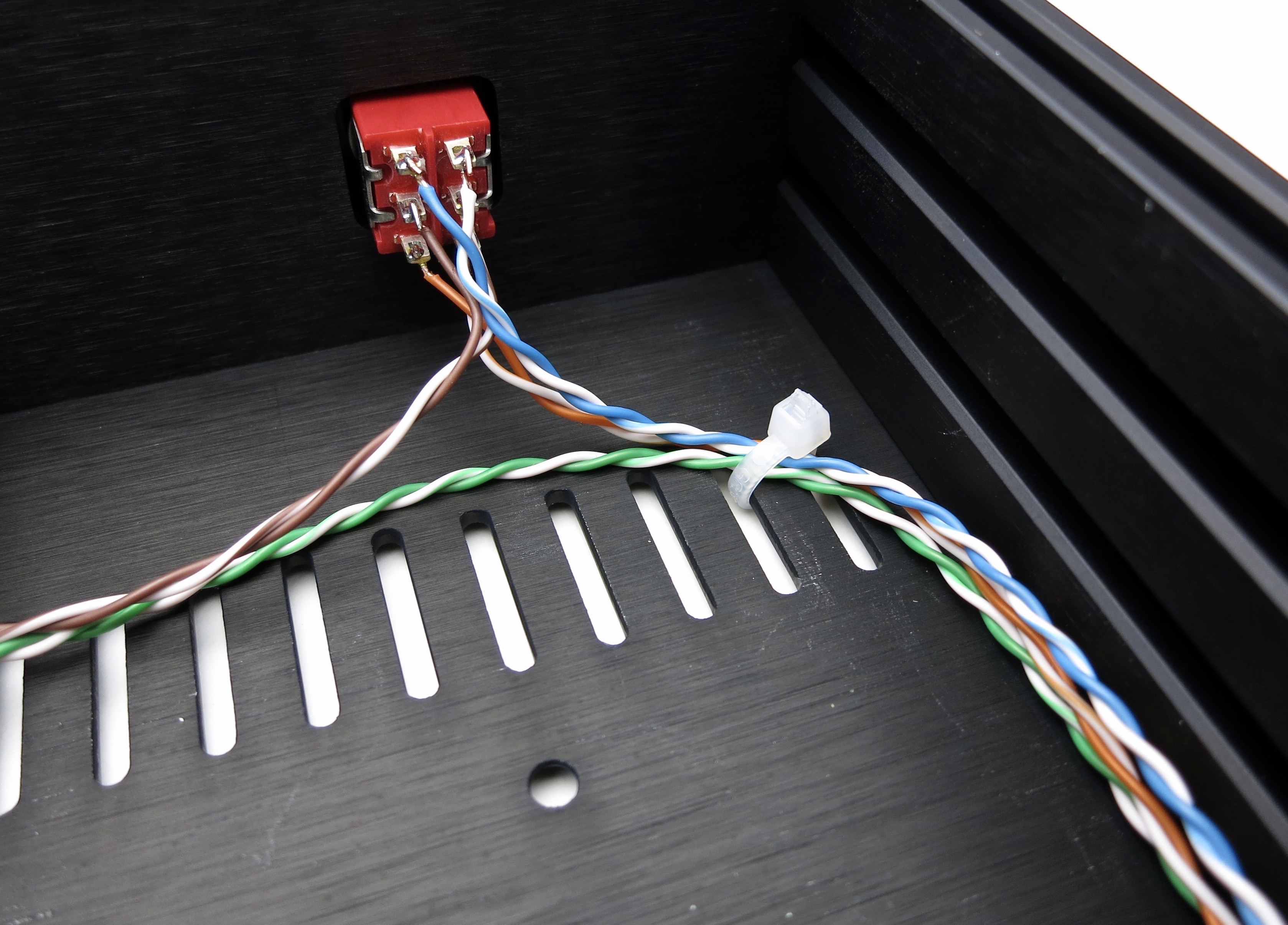
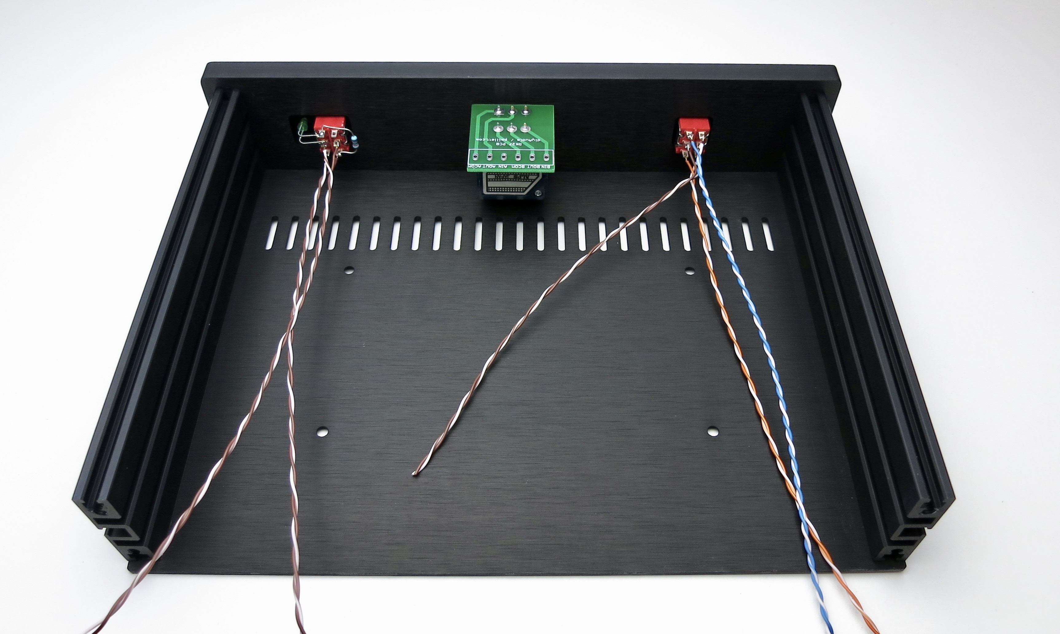
Wire routing
Remember green is input grounds, and go directly to the potentiometer.
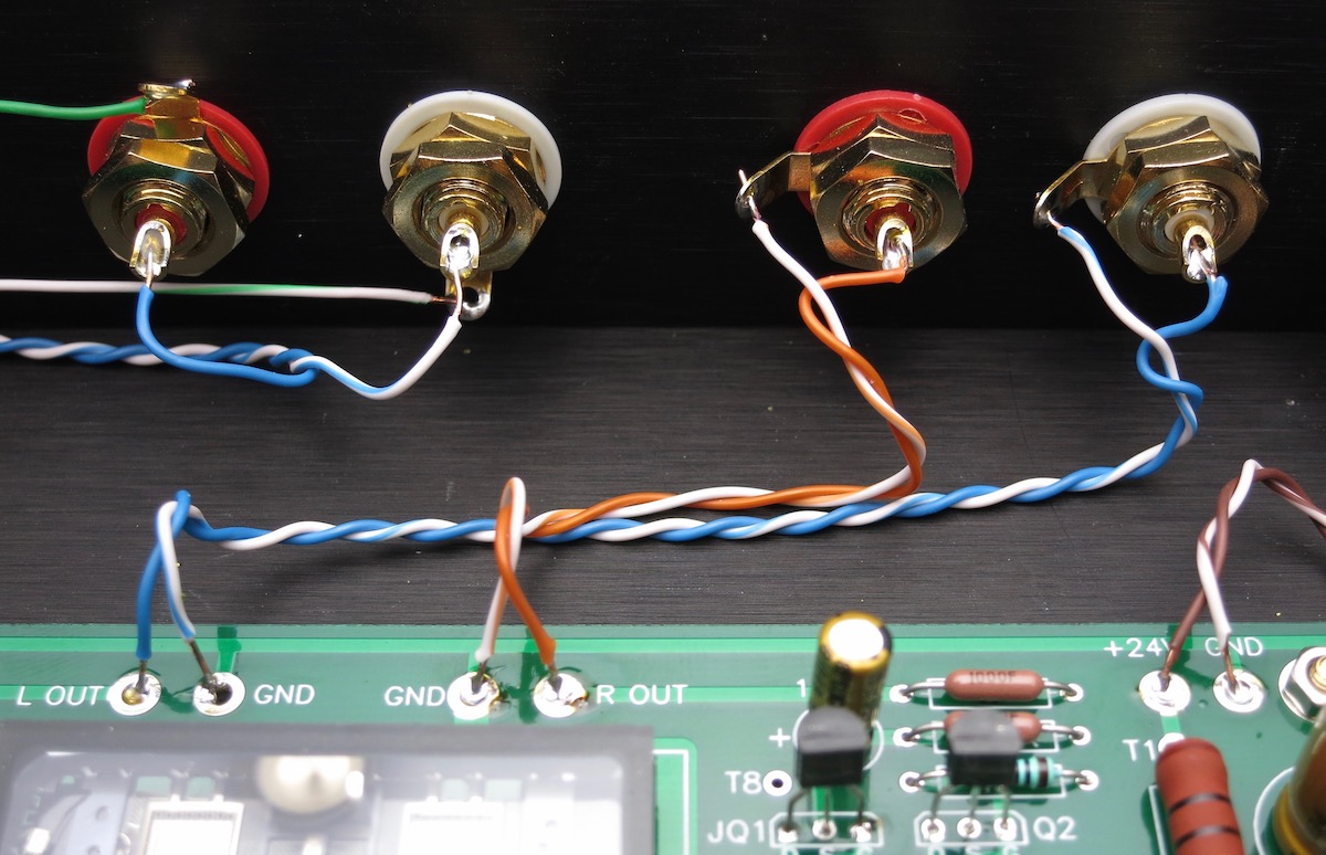
Rear panel
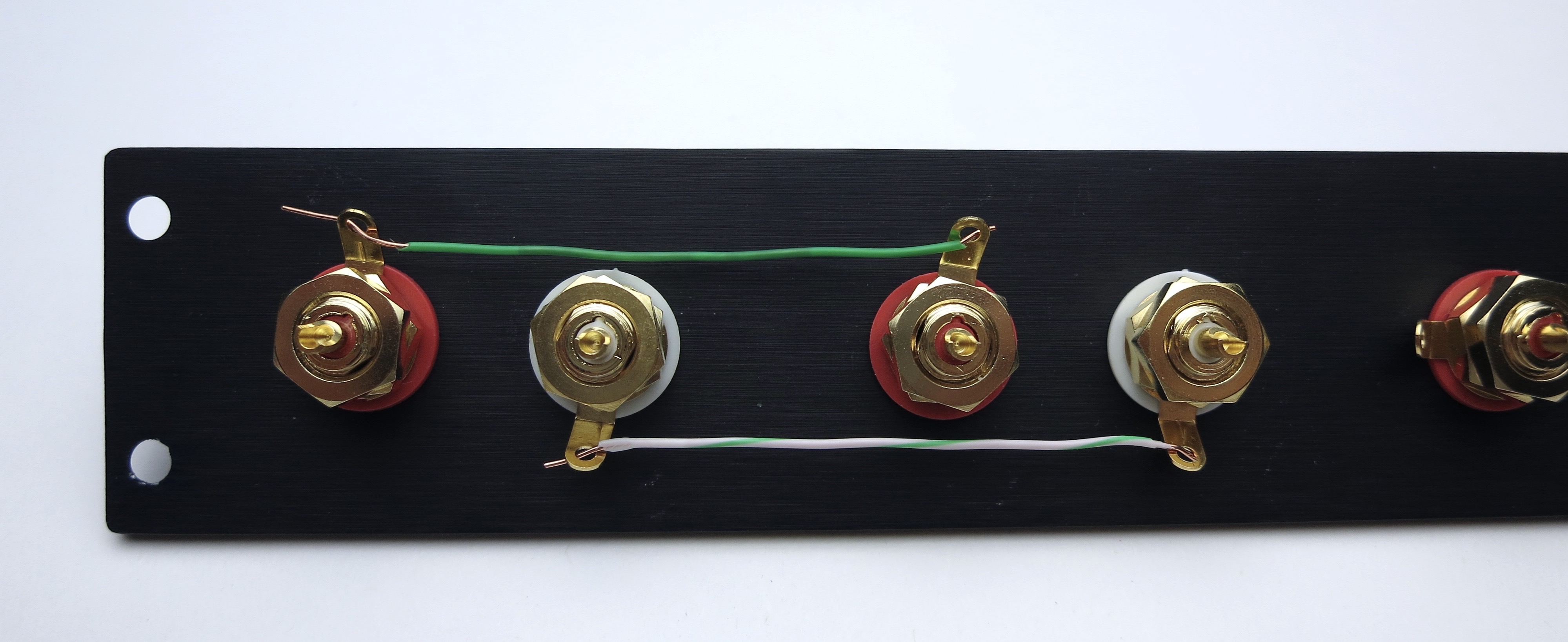
Ground tabs tied together as shown. Solid green to right ground tabs, white/grn to left tabs
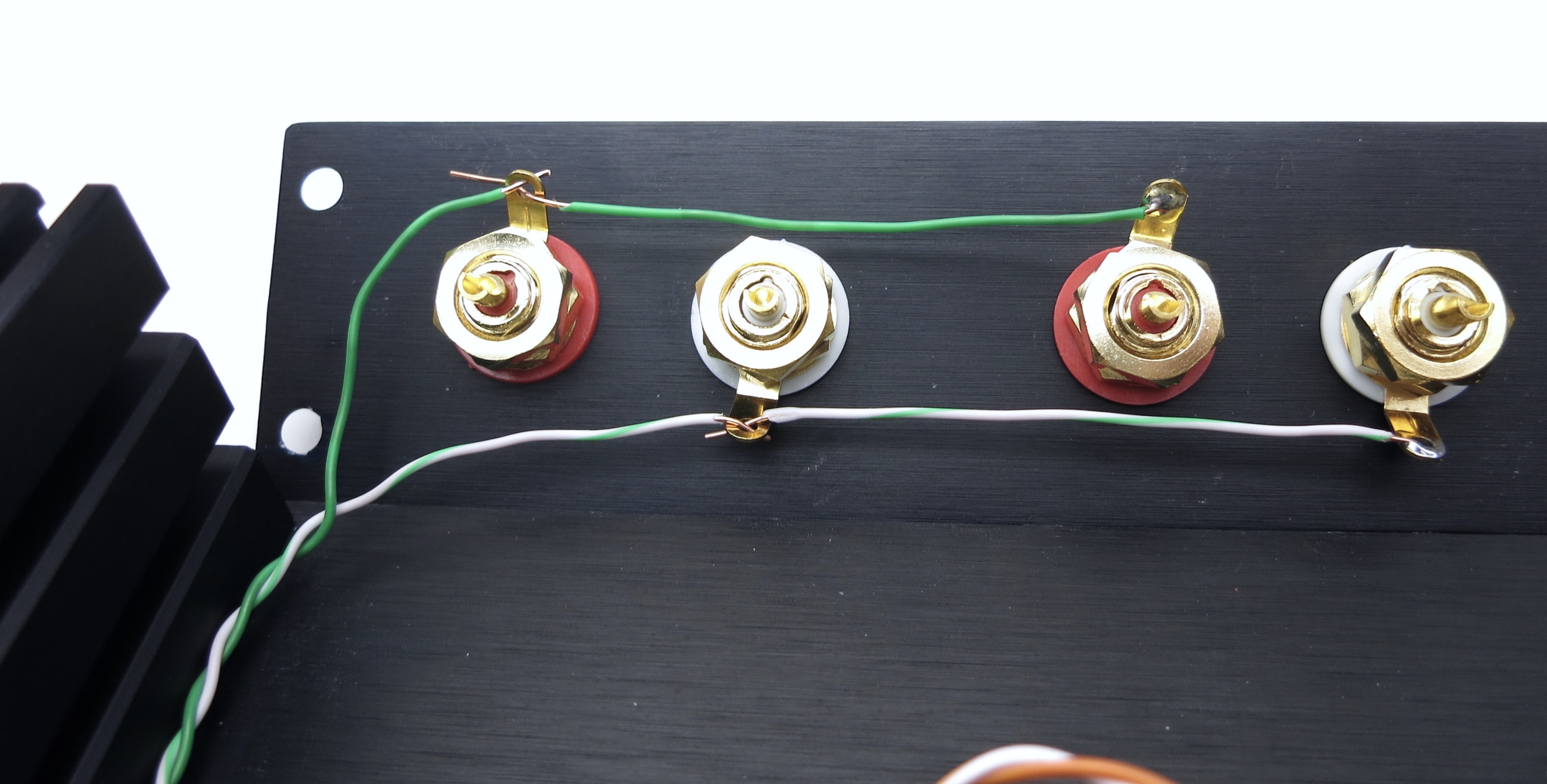
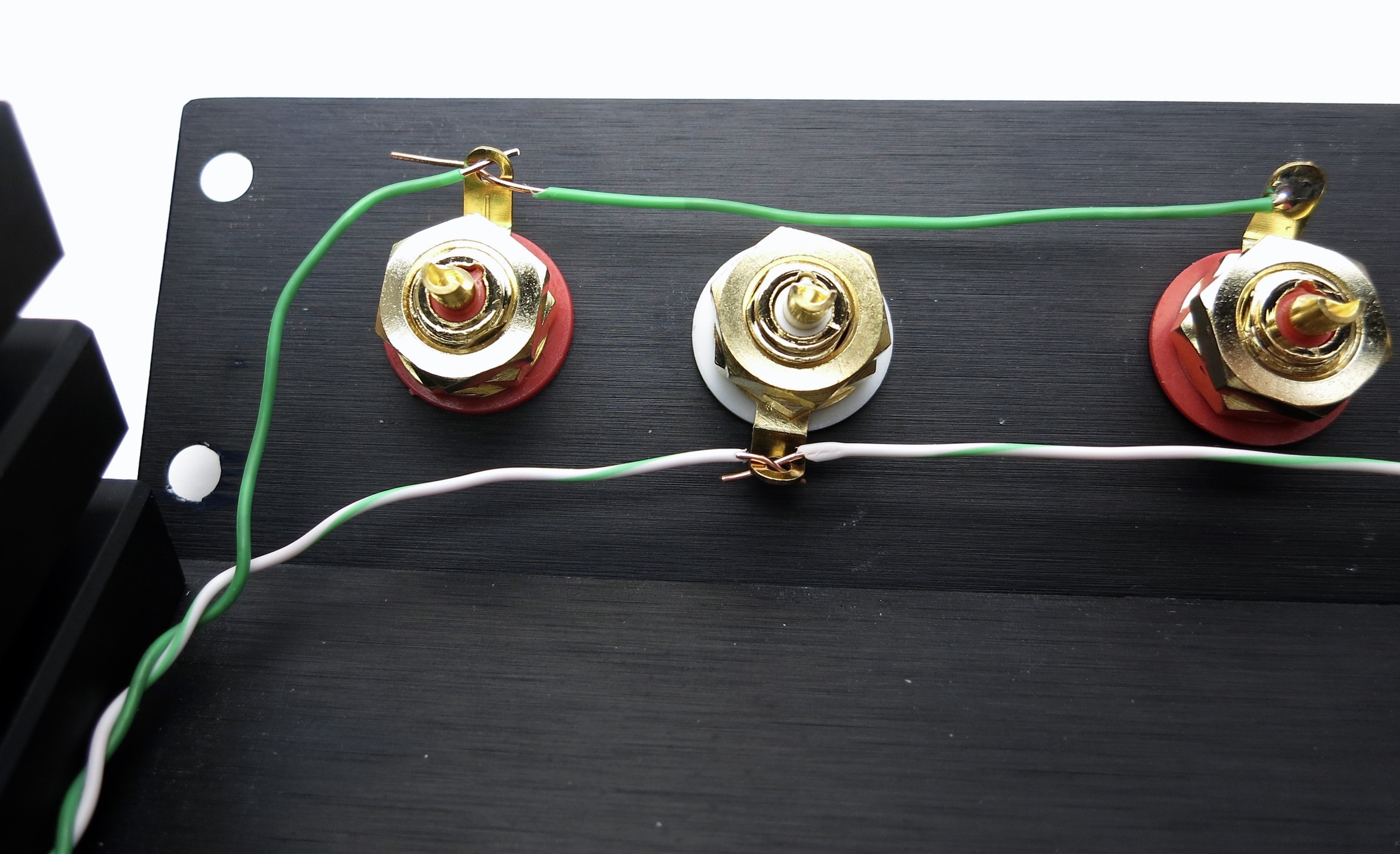
Orange is input one. Solid is right
Orange is input one. Solid orange to right, white/orange to left.
Blue is input 2. Solid blue to right, white/blu to left.
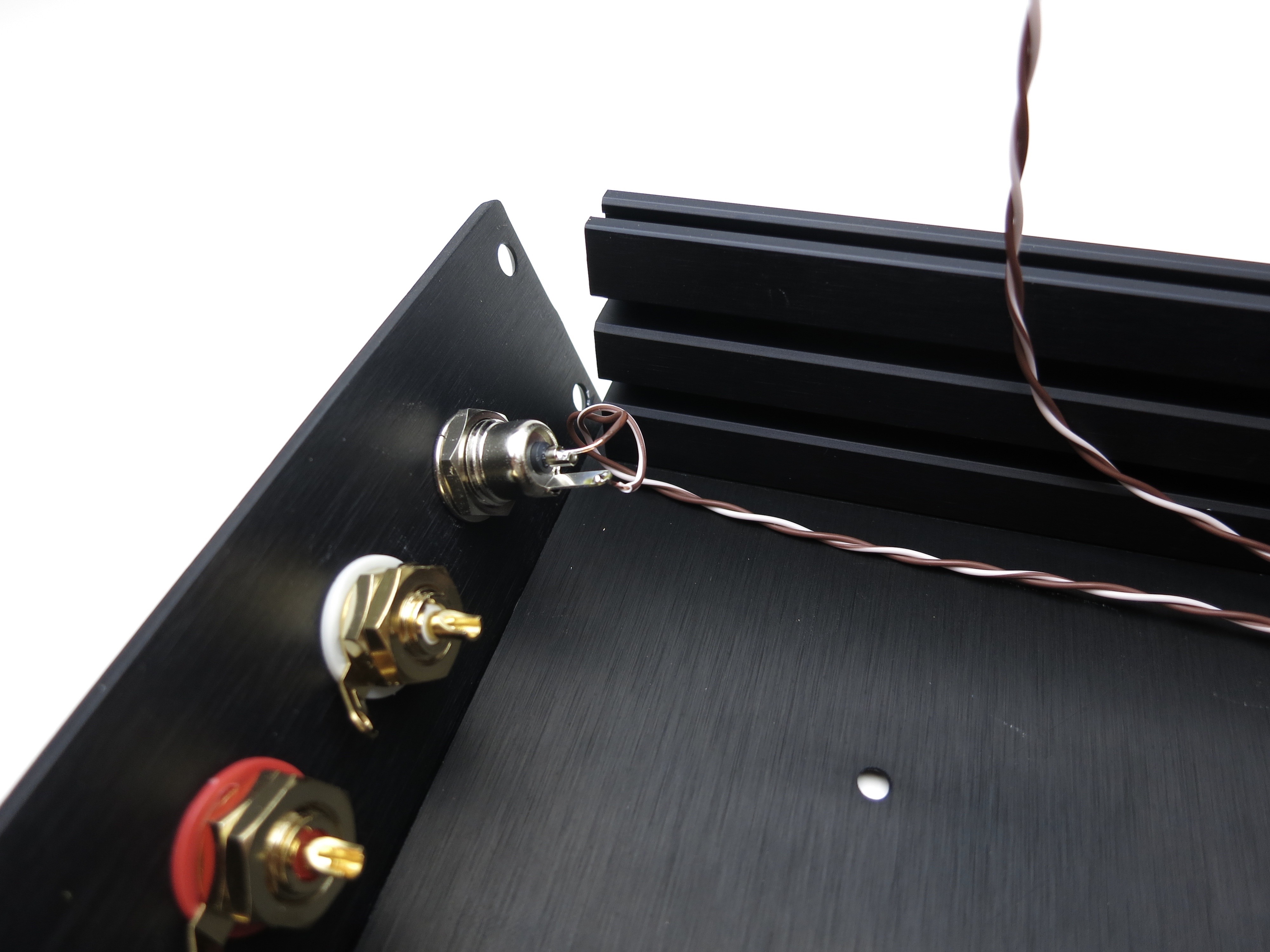
Wires to middle of front panel power switch. Brown is barrel center, white/brn is tab.
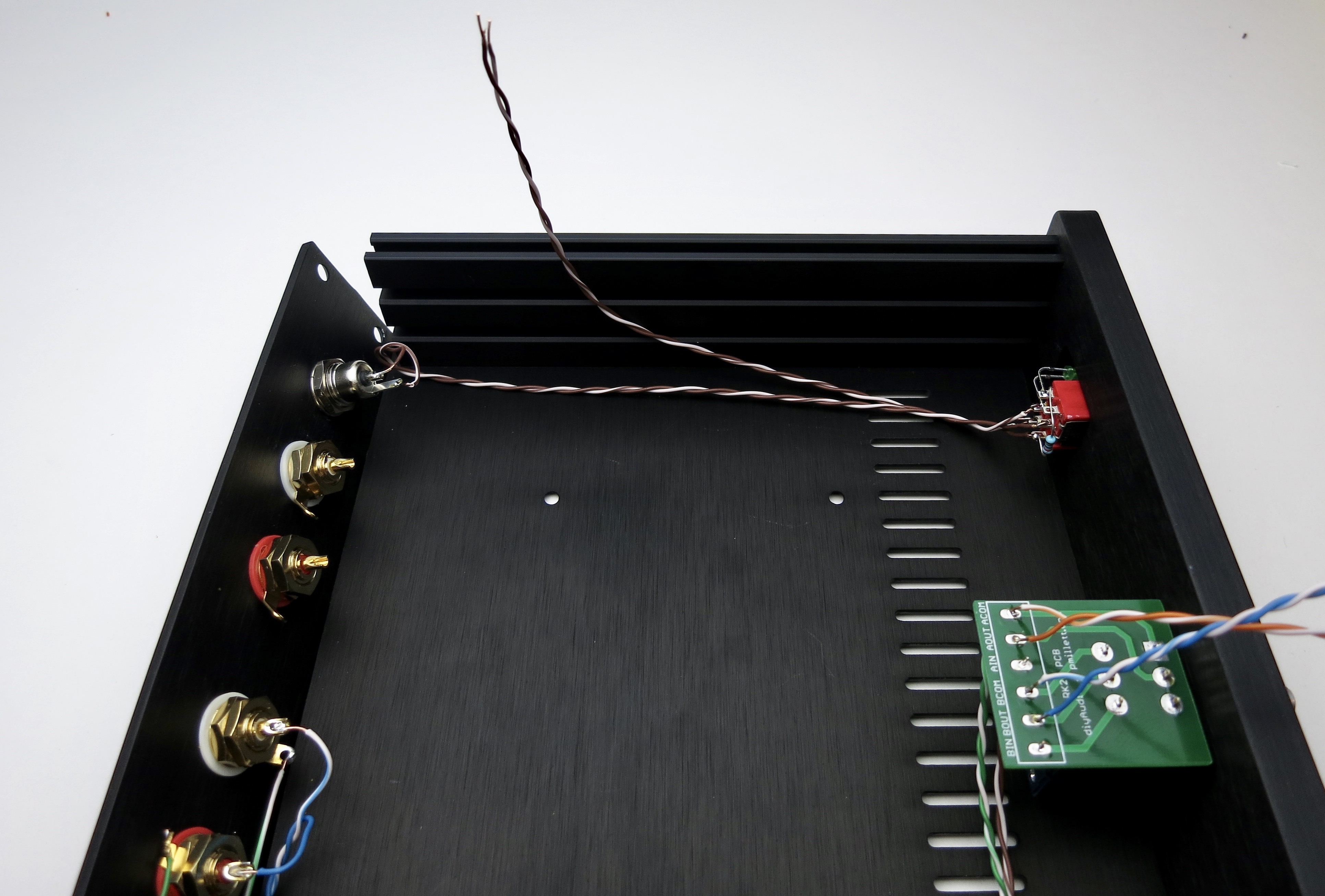
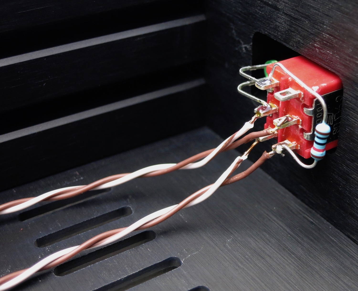
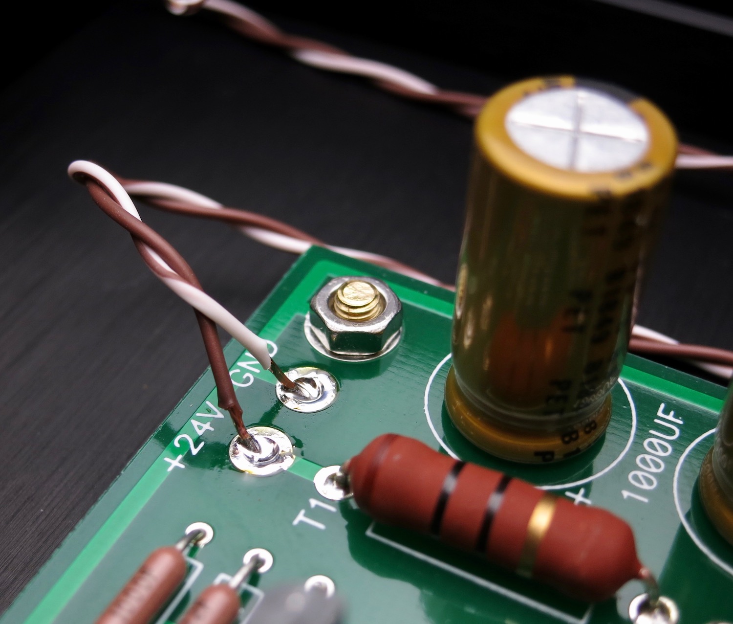
Wires from the bottom of this switch connect to the PCB. Brown is +24V, brown/wht is GND
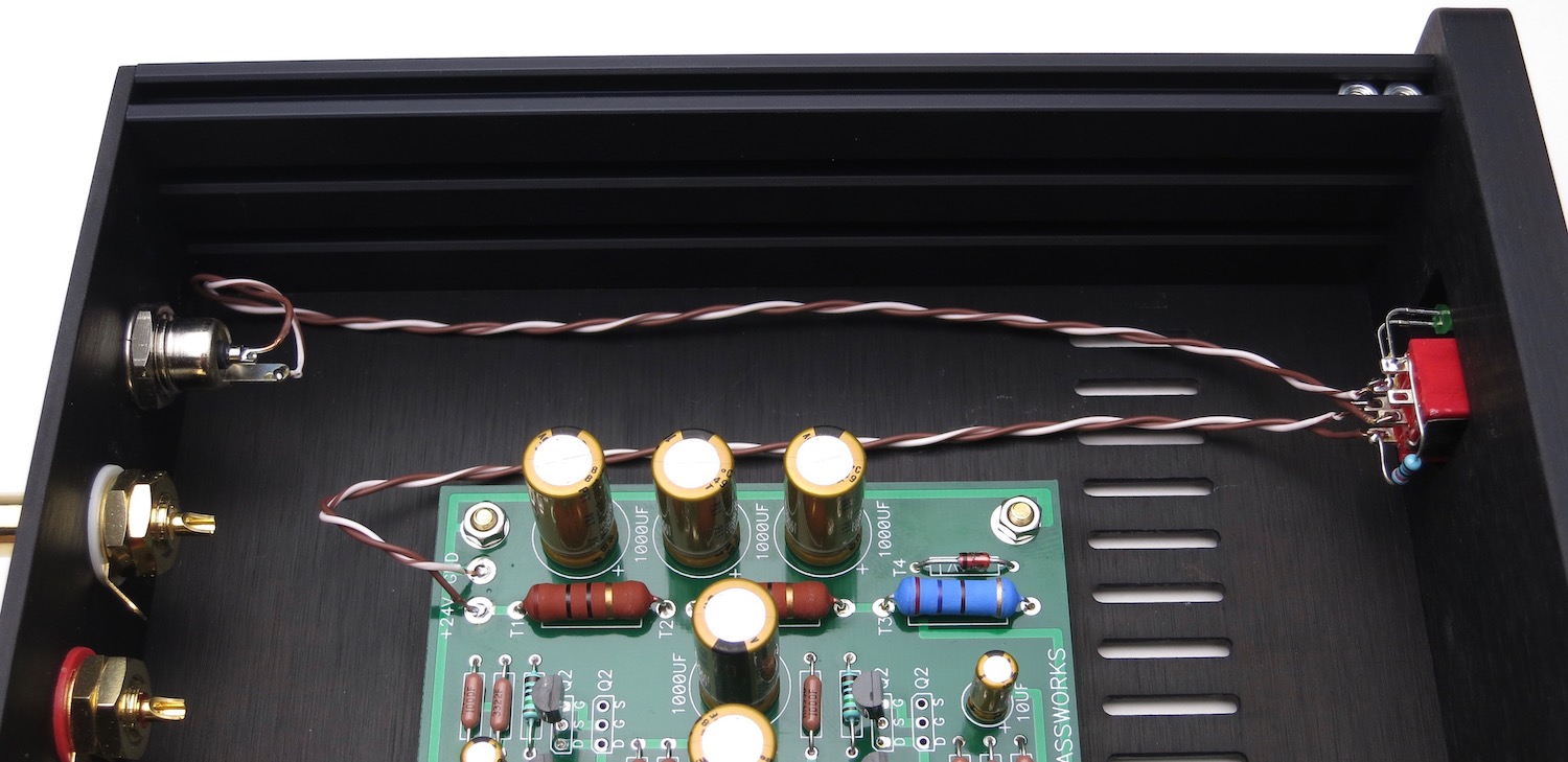
The photos of the Barrel-Power Switch-PCB wiring are for clarification. PCB Stuffing, starting with the PSU is next.
The middle of the switch need to be connected to the IN pads of the pot board. In our wiring scheme so far, solid colors are right and white/trace color are left
Grounds are connected to the COM pads and go directly to the input RCAs, not connecting to the switch. Solid green is right, white/green left.
Do not solder yet!
Color coding is changing, sorry... Orange for right (because it's closer ro red) and Blue for left.
Positive is solid, white/trace GND
Solids to OUT, whites to COM
Solder all 6 positions now
Wire routing
Remember green is input grounds, and go directly to the potentiometer.
Rear panel
Ground tabs tied together as shown. Solid green to right ground tabs, white/grn to left tabs
Orange is input one. Solid is right
Orange is input one. Solid orange to right, white/orange to left.
Blue is input 2. Solid blue to right, white/blu to left.
Wires to middle of front panel power switch. Brown is barrel center, white/brn is tab.
Wires from the bottom of this switch connect to the PCB. Brown is +24V, brown/wht is GND
The photos of the Barrel-Power Switch-PCB wiring are for clarification. PCB Stuffing, starting with the PSU is next.
Last edited:
Add photo for "measure EVERY resistor before stuffing"
PCB STUFFING
PSU section is stuffed and tested first. Please do not stuff entire PCB at once.
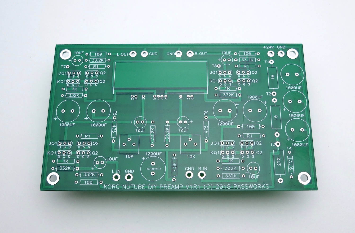
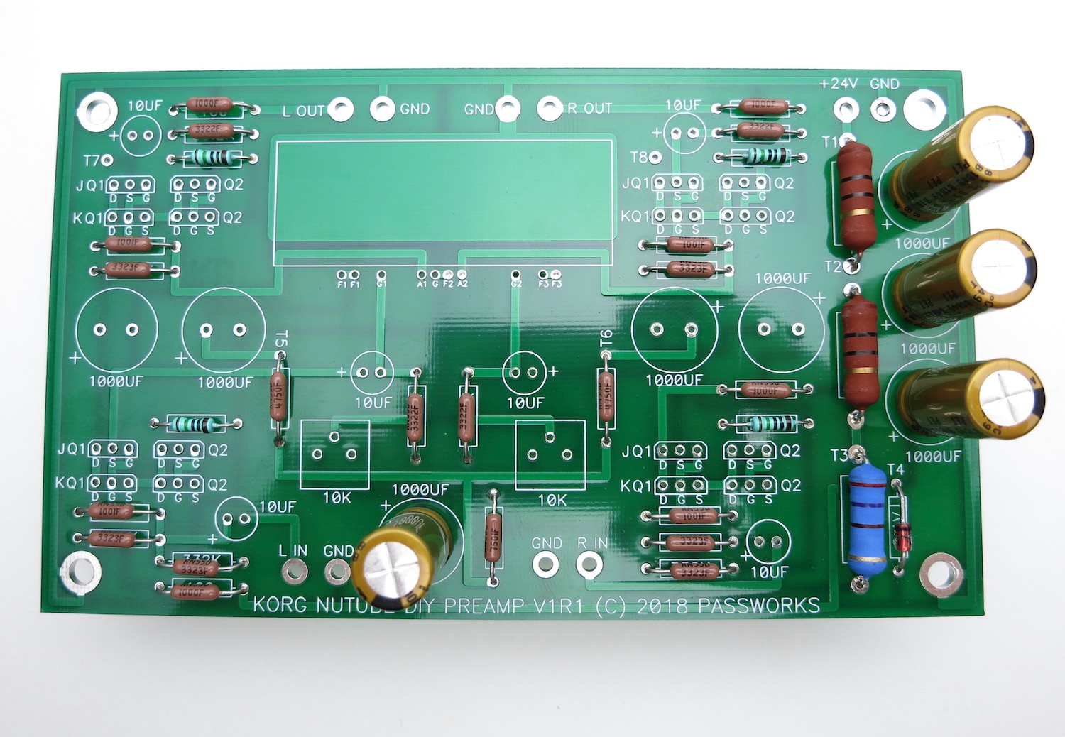
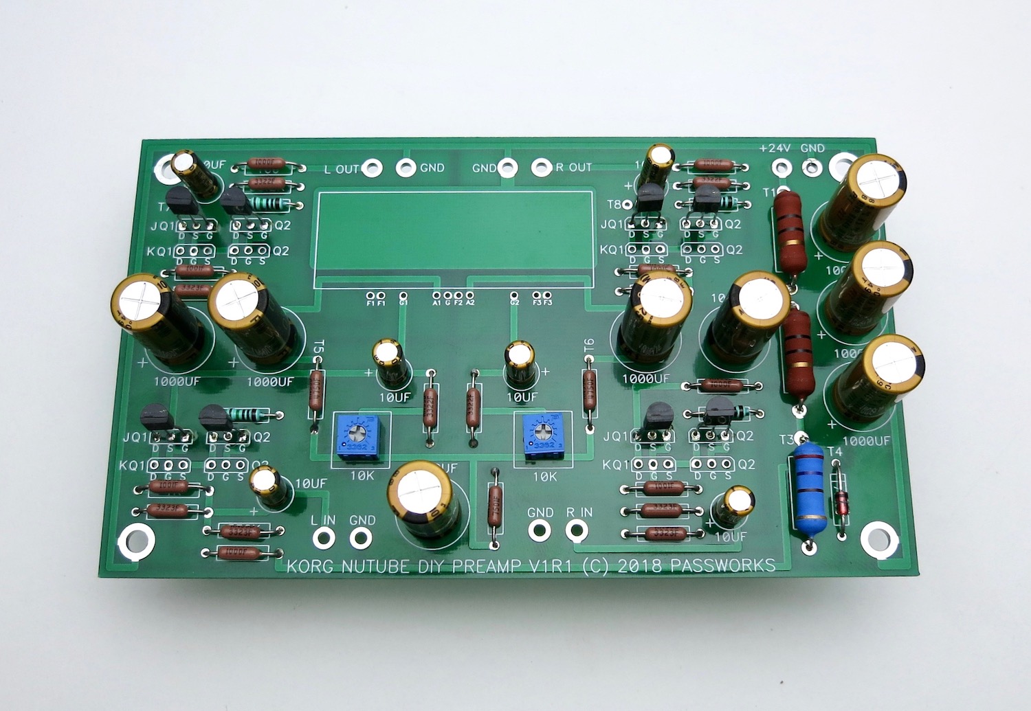
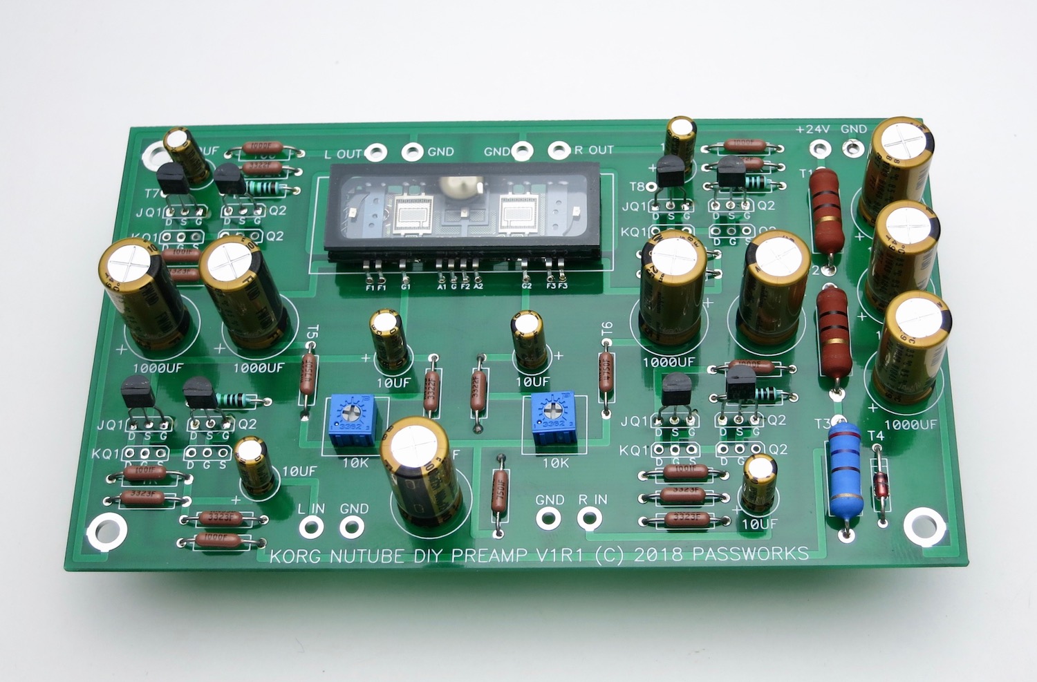
Bare PCB
V1R1 is the most current as of this writing (Spring 2020)
We need to assemble and test the PSU first.
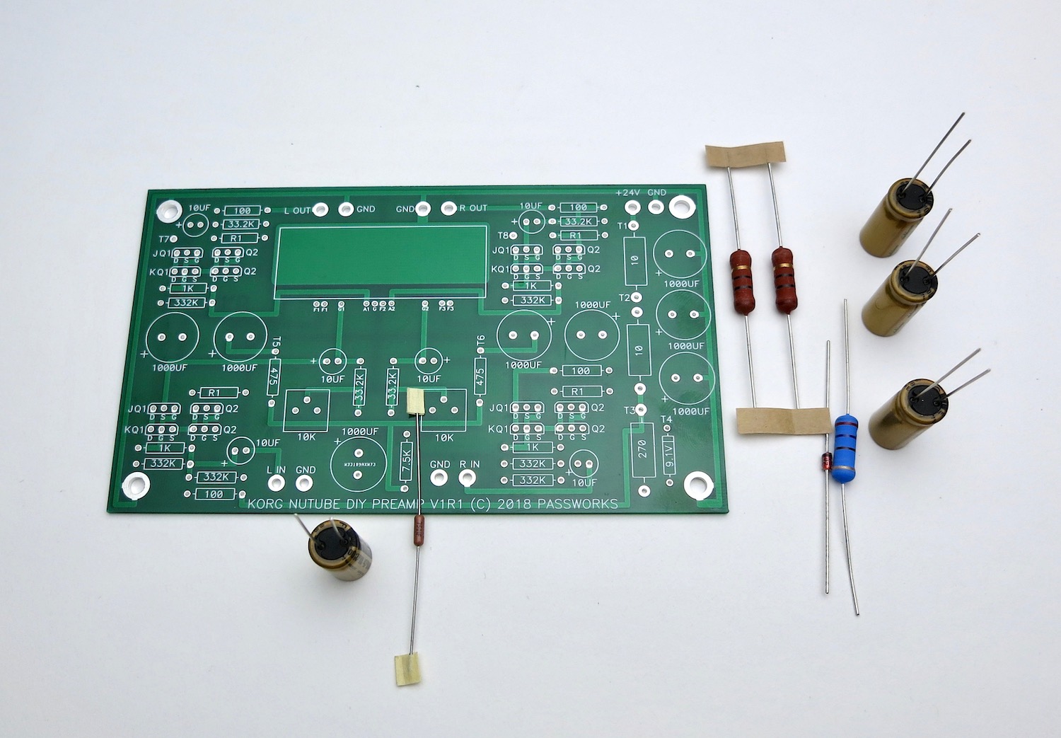
Get these components, they are in the top part of the schematic. This section is common to both L and R channels.
As always, print this out and have in front of you as you build.
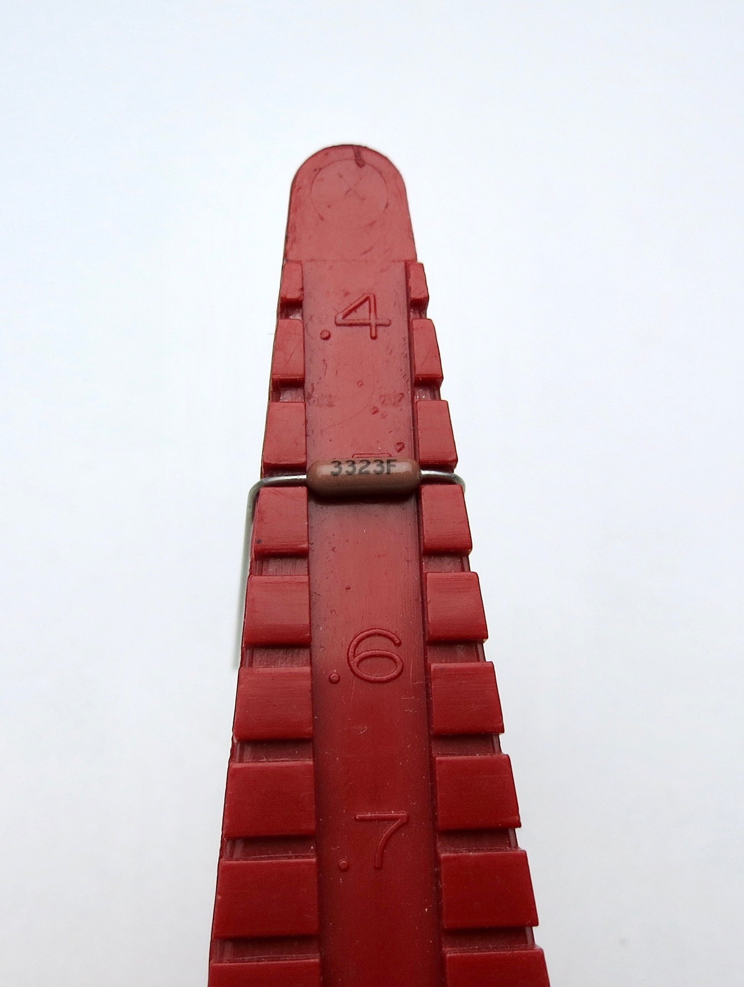
If you have a lead bend tool, the small resistors and diode are on 0.5" spacing.
The large resistors are 0.75", but you can just bend those leads straight down and it will be close enough.
Capacitors have polarity. The negative is marked on the can, and the positive is the long leg. Also note the PCB has the + marked.
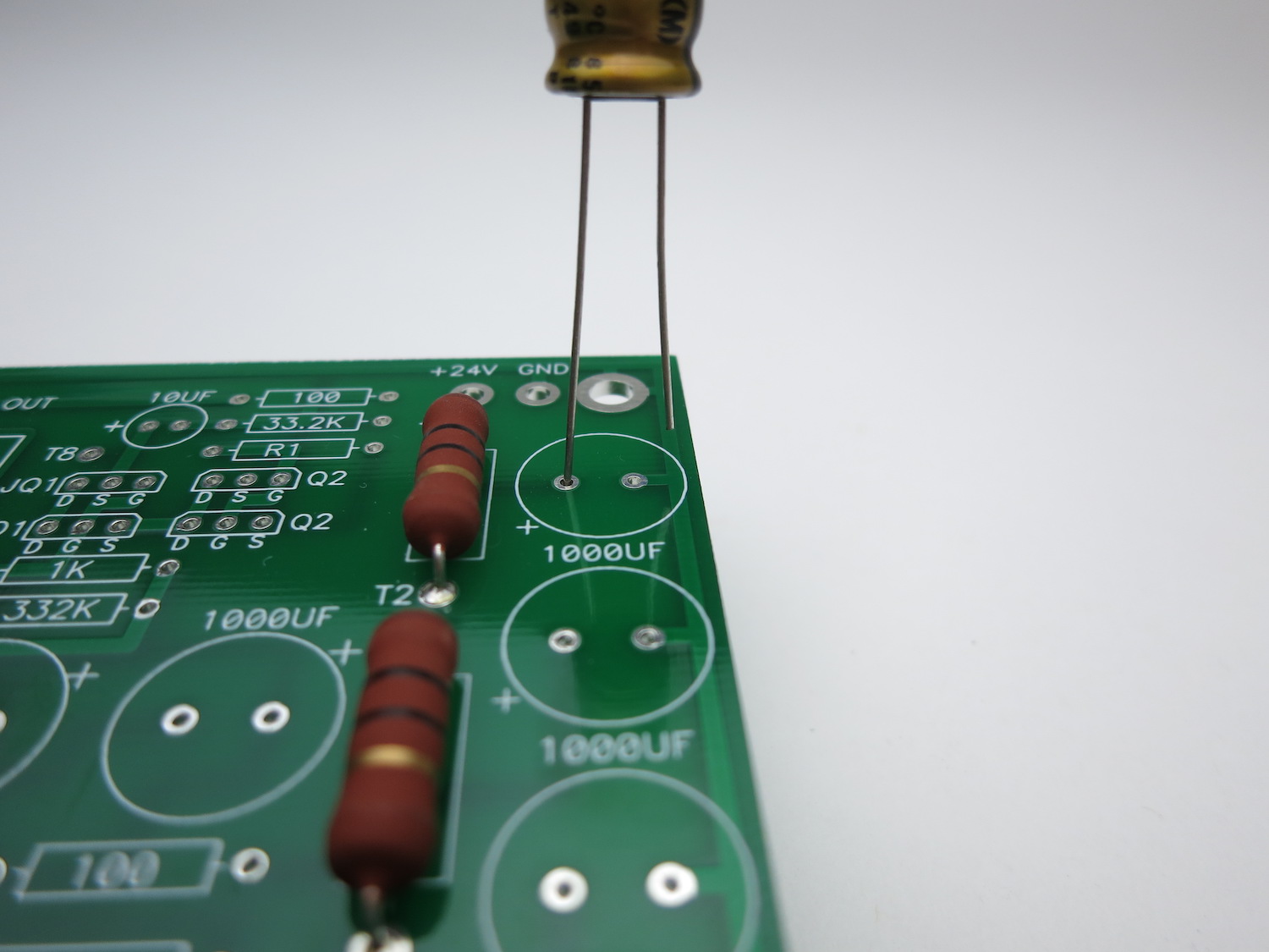
Long leg into +
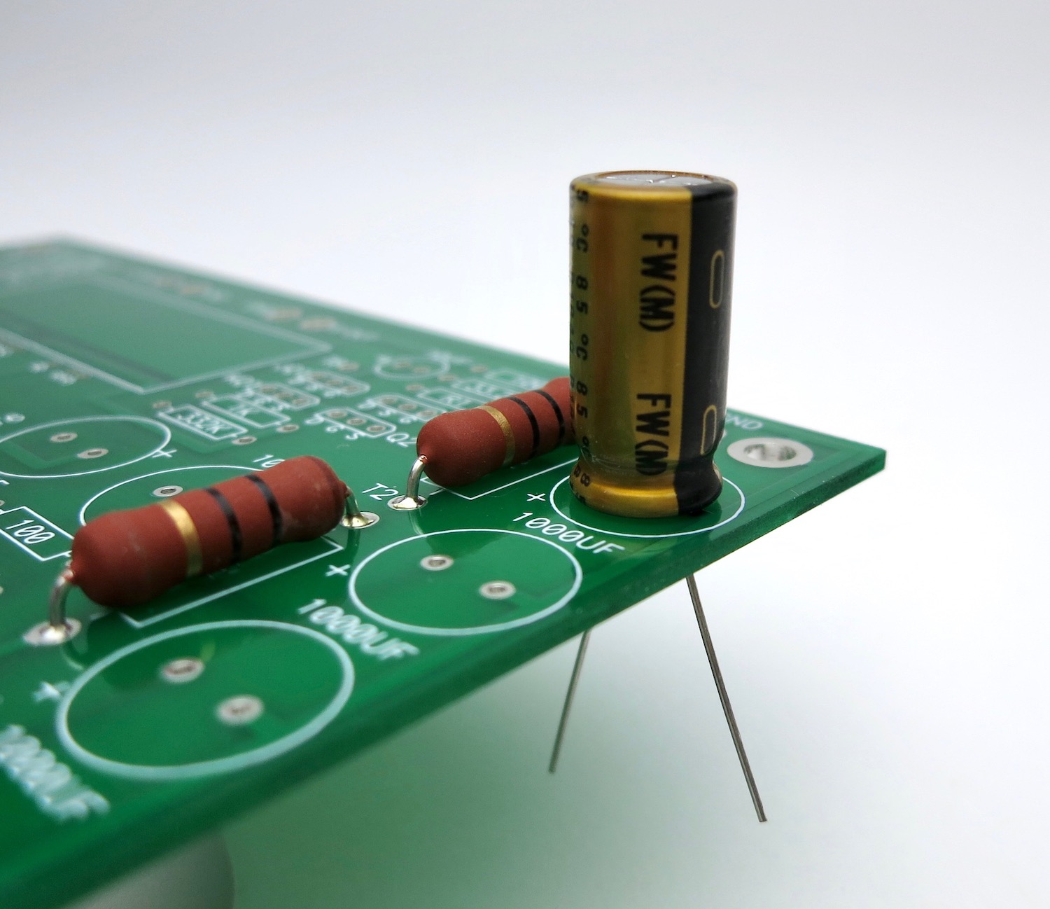
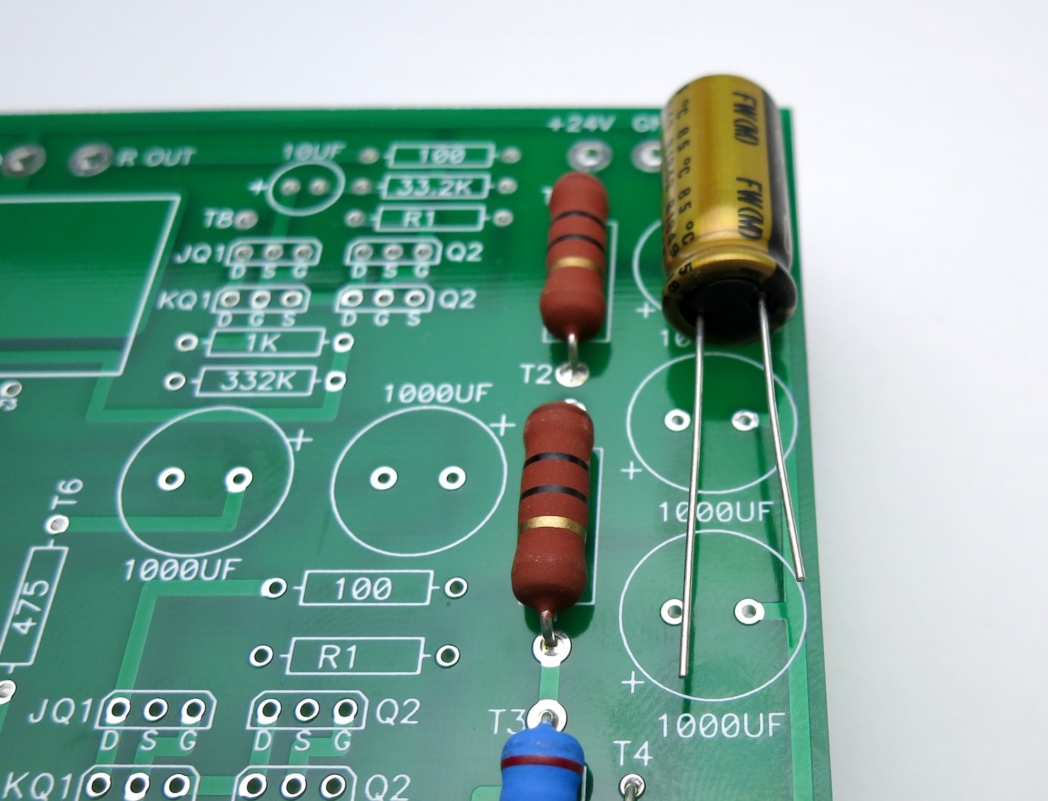
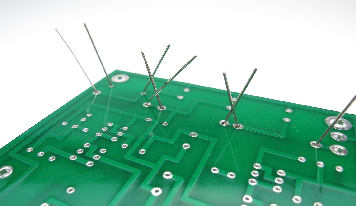
Bend the leads out a little to keep the components in the PCB before soldering.
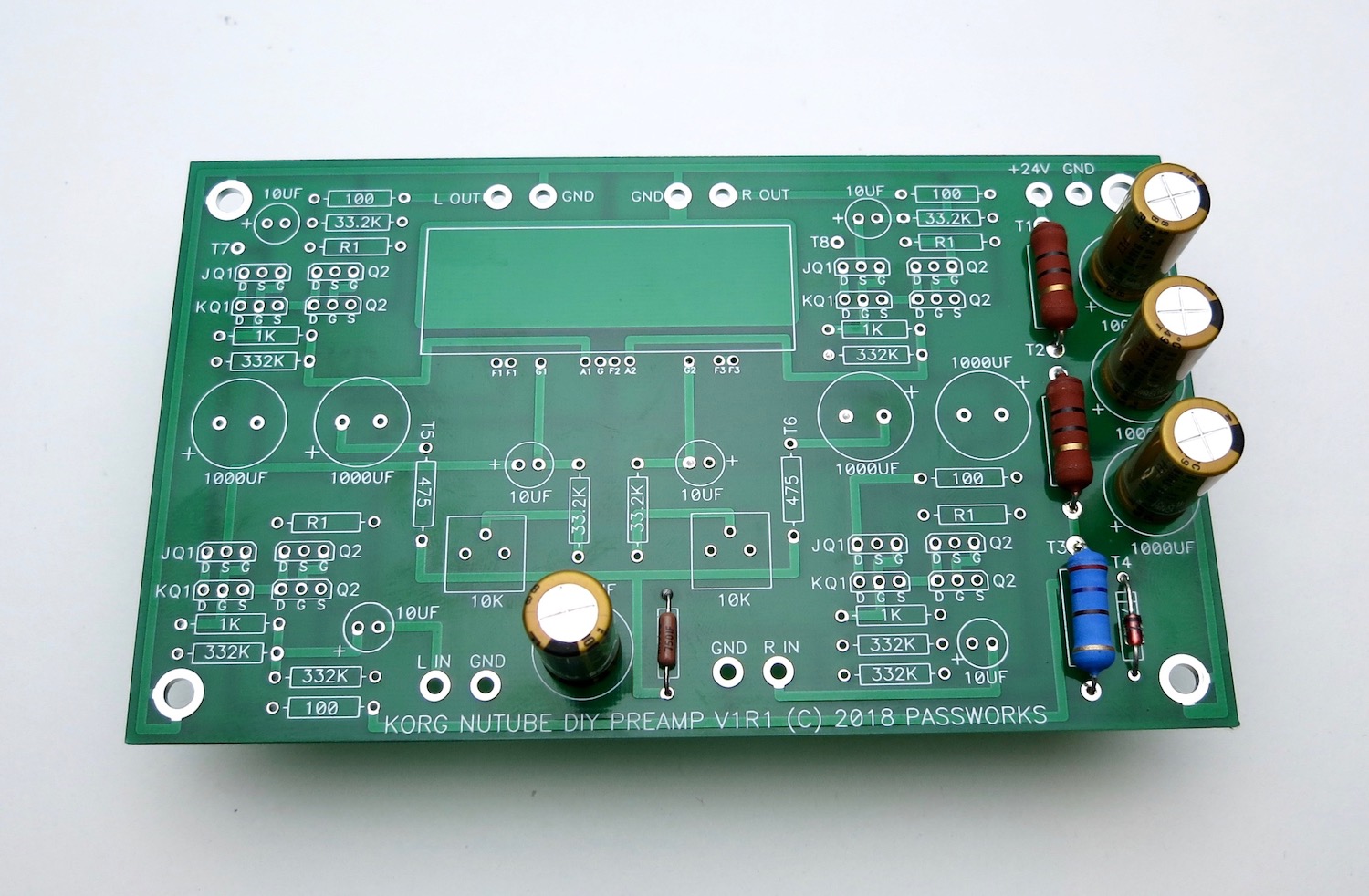
When you get these components stuffed stop and test the PSU.
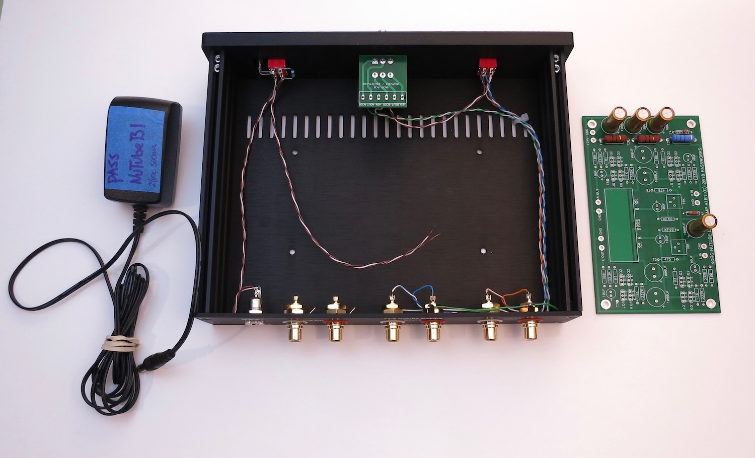
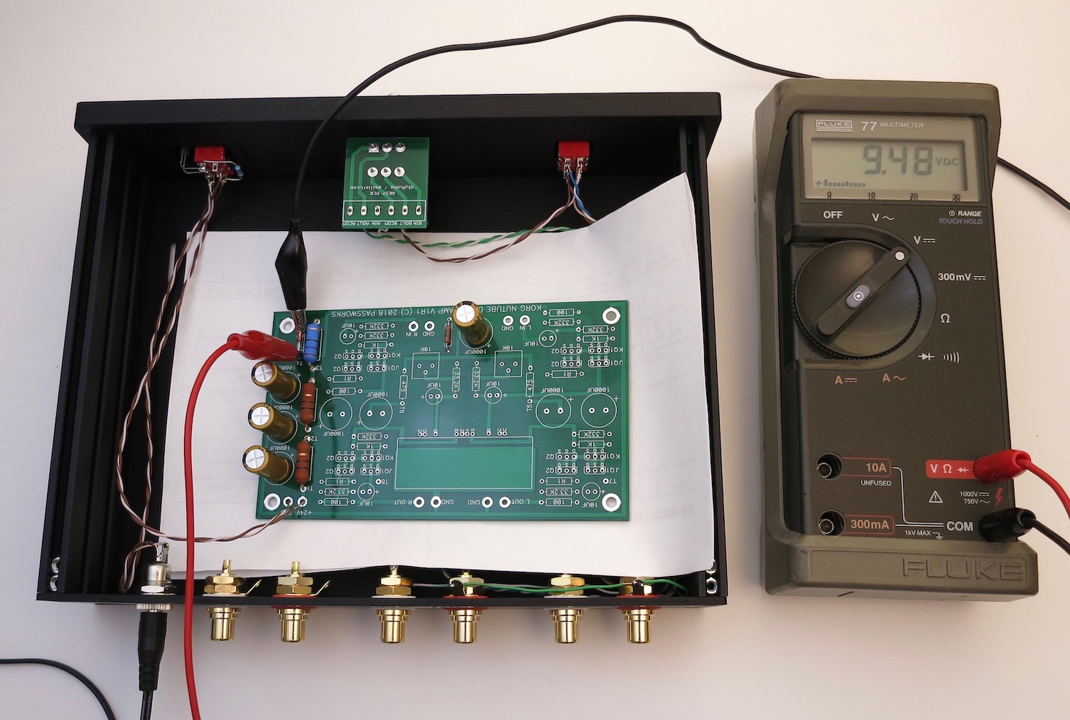
Get the wall wart, the wired chassis, a piece of paper or something non-conductive to insulate the board from the metal, and the PCB
Wires from middle of power switch. Brown is barrel center, white/brn is tab.
Wires from middle of power switch. Brown is barrel center, white/brn is tab.
Wires from bottom of switch to the PCB. Brown is +24V, brown/wht is GND
Attach PSU switch as shown.
Ignore the fully stuffed PCB in the photo, it should only have PSU components on it right now!!
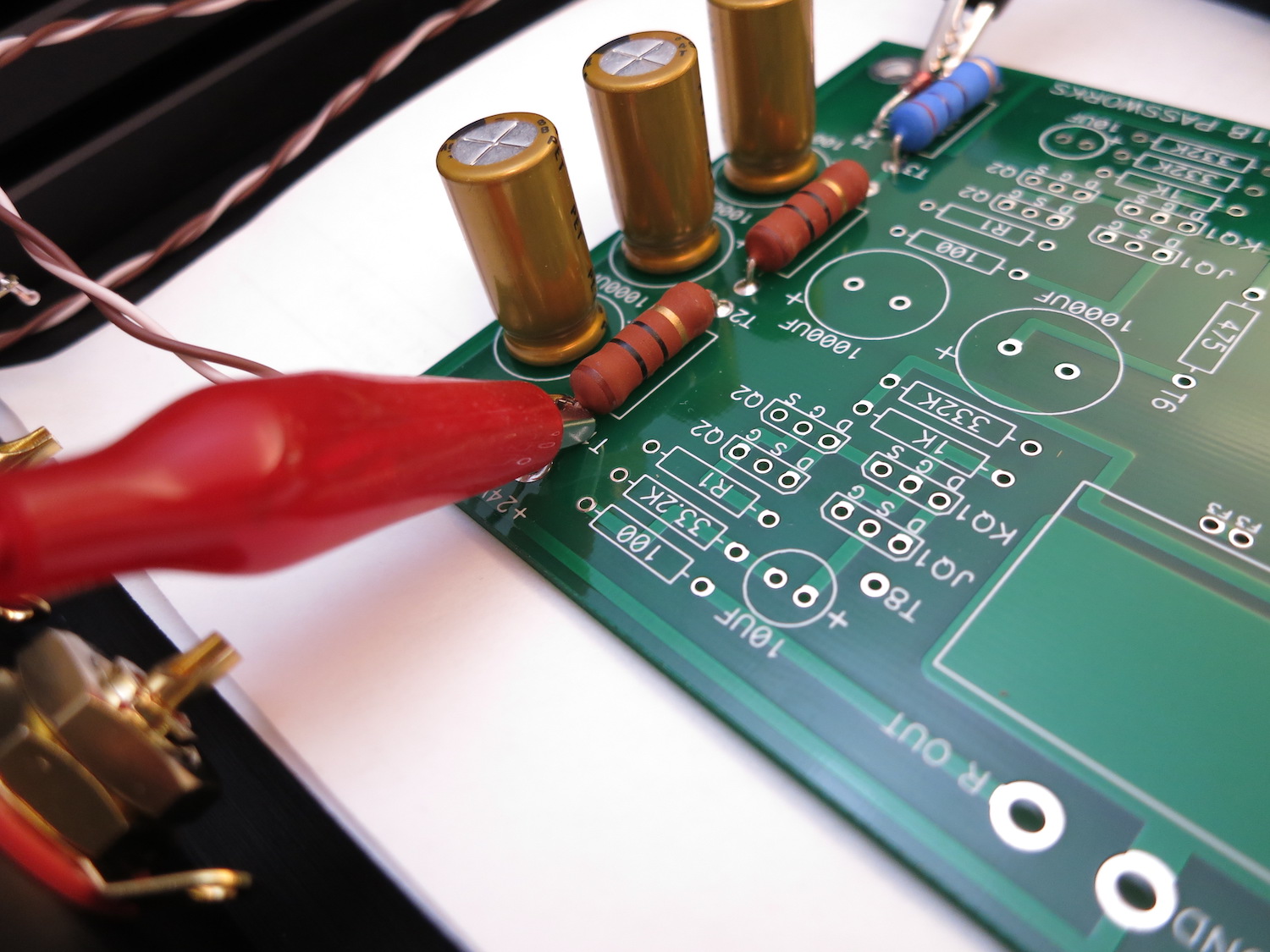
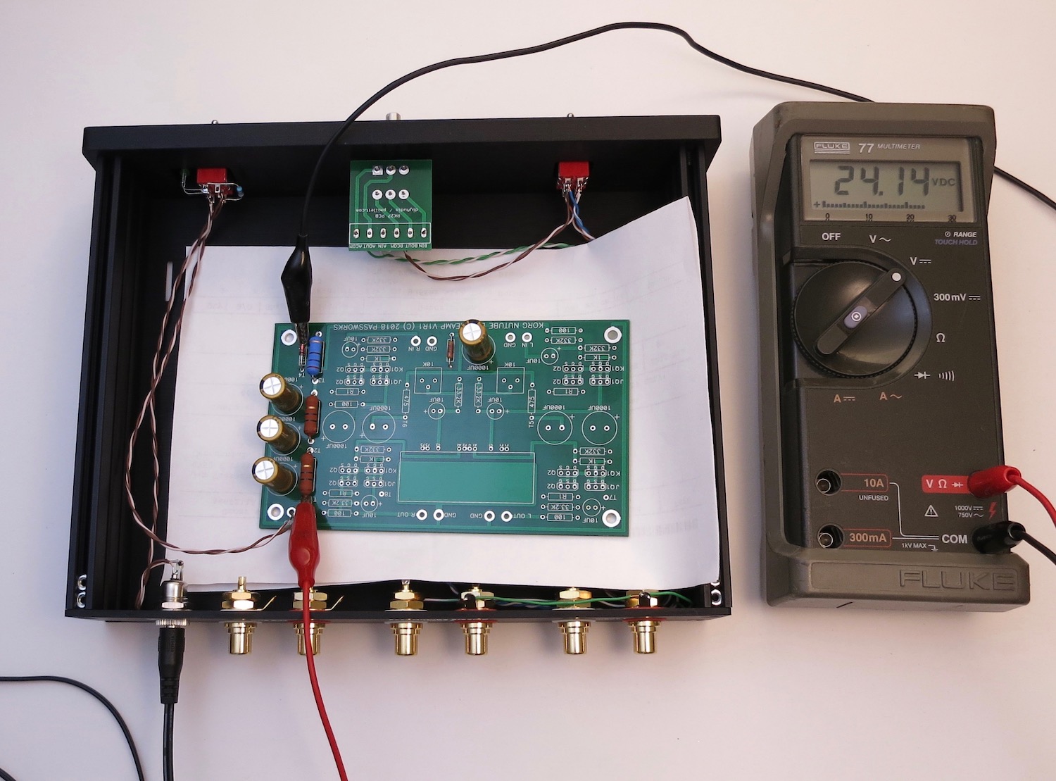
Connect the power switch wires to the PCB and power it on. Connect meter to places shown and you should have about 24V.
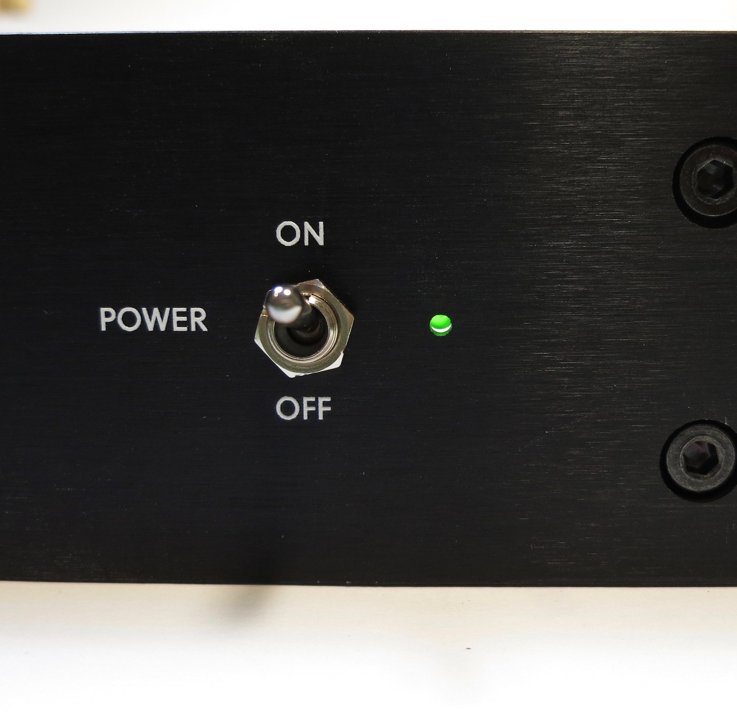
Also check the chassis LED
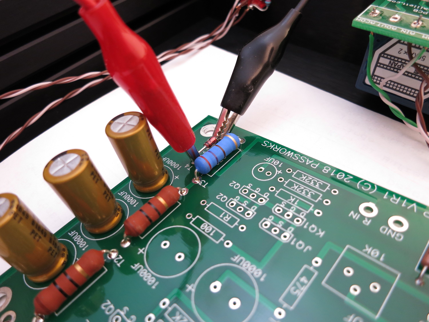
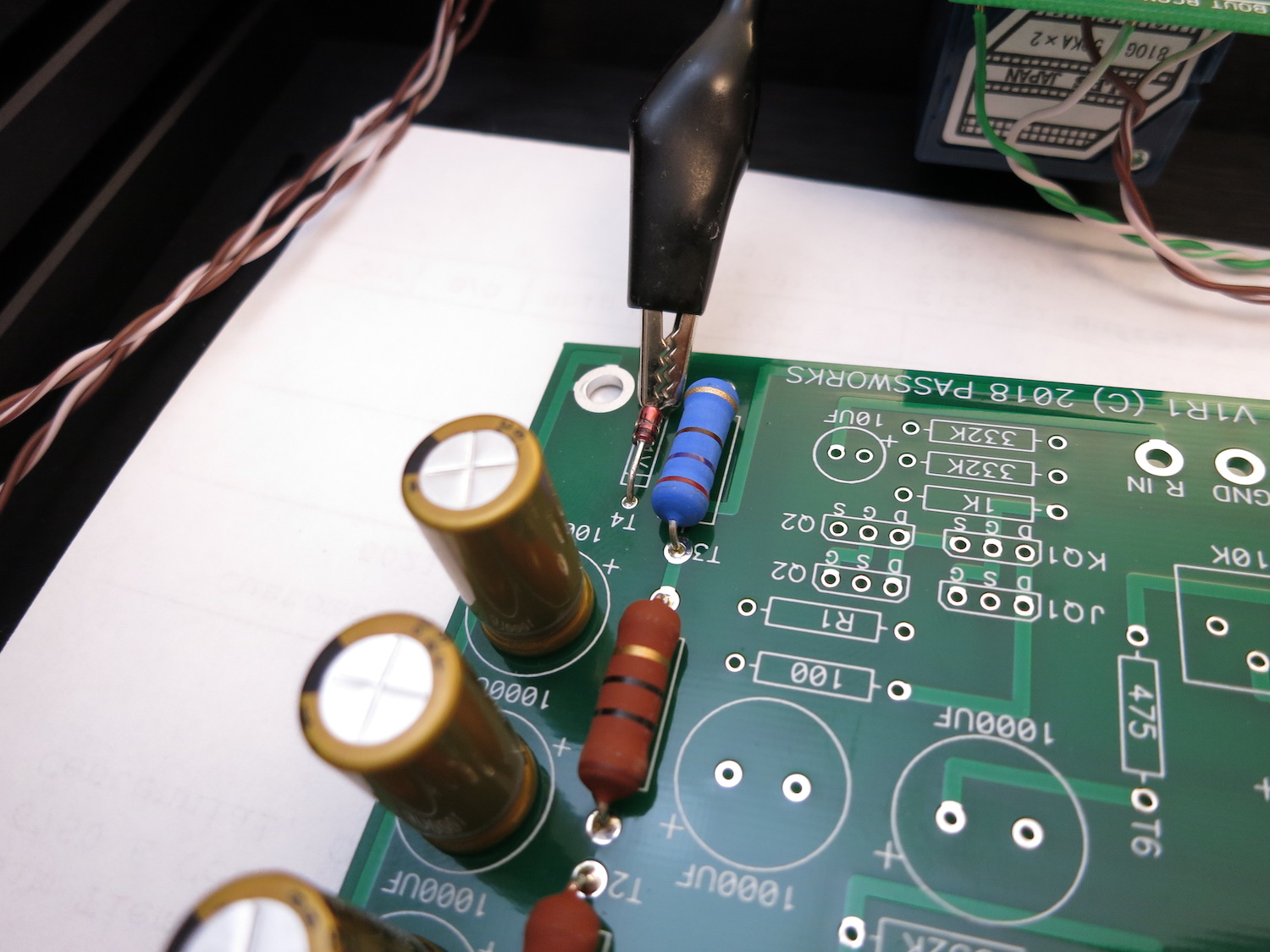
Move the multimeter red to the top (black band) leg of the diode and check the voltage of about 9.5V
If you have these readings, turn it all off, unsolder the Main PCB from the wires and continue.
Last edited:
Stuffing PCB part 2
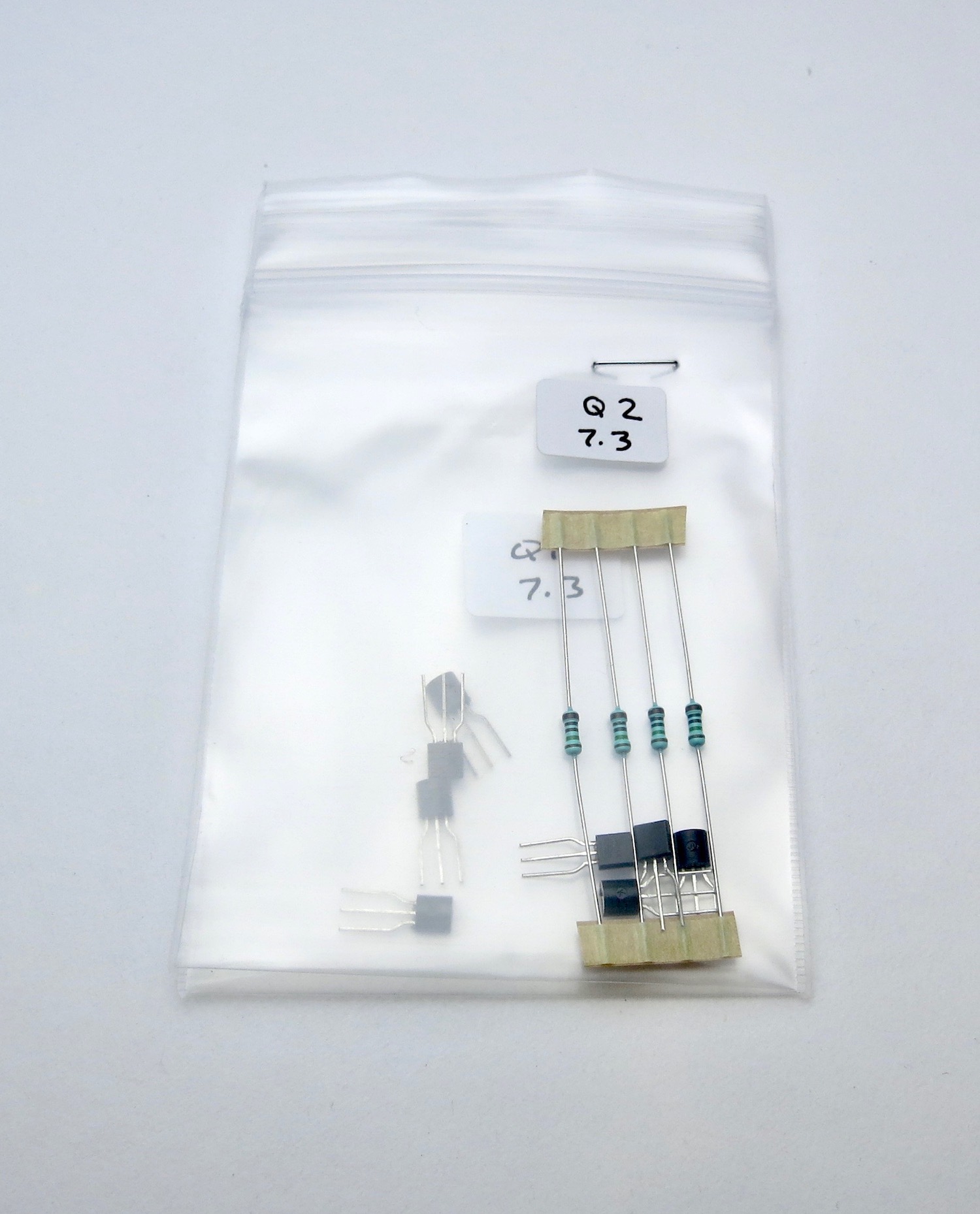
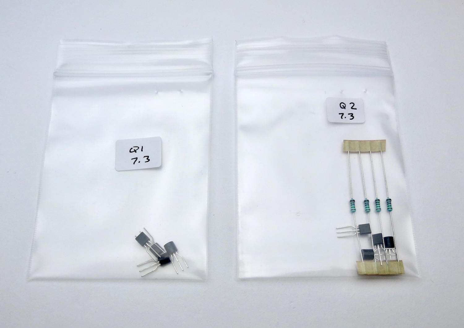
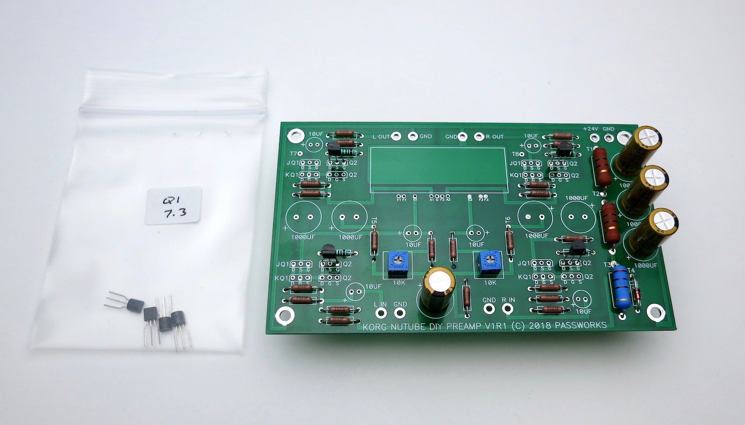
The PCB kit comes with two bags and resistors, don't mix them up, and don't lose the resistors, as they are selected for those specific transistors, in your kit.
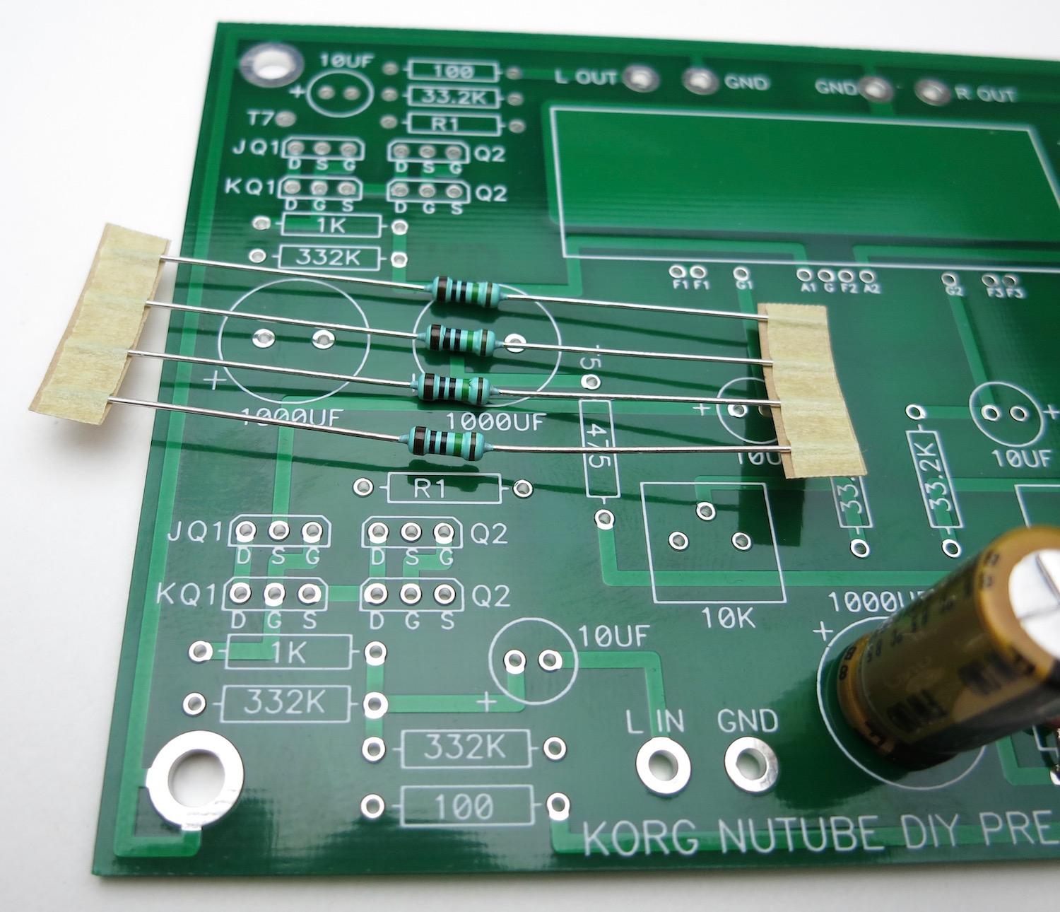
The resistors go into the spot marked "R1" on the PCB, there are (4) places. These locations have no value printed on them nor does the schematic have a value. They are selected to mate with the included transistors.
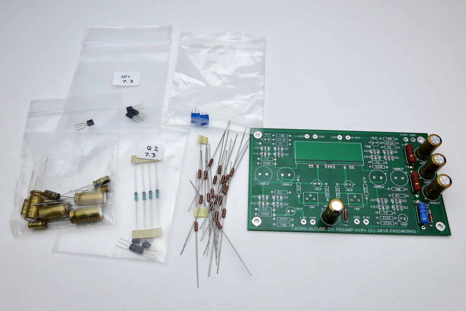
Gather the rest of the PCB parts
As mentioned earlier, the resistors are all on 0.5" lead spacing
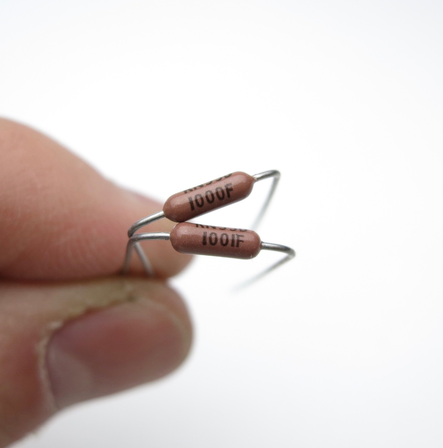
The Dale resistors have their value marked in digits on the side
This is 3-digit+multiplier
The top resistor is 100 ohms -- 100+0, or "one hundred ohms and zero zeroes"
The bottom is 1K -- 100+1, "one hundred and one zero"
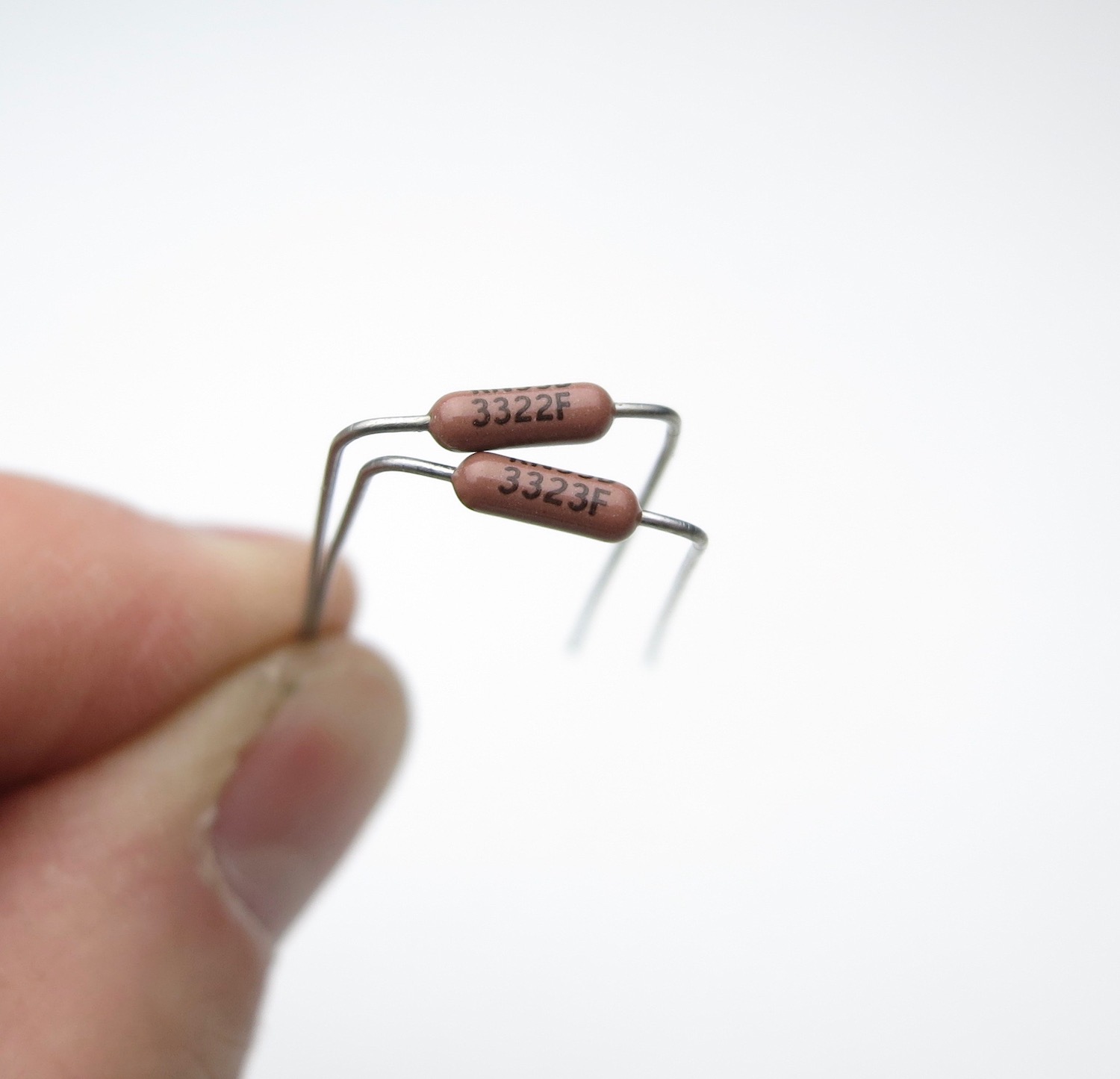
Top 33.2K "332 + two zeroes"
Bottom 332K "332 + three zeroes"
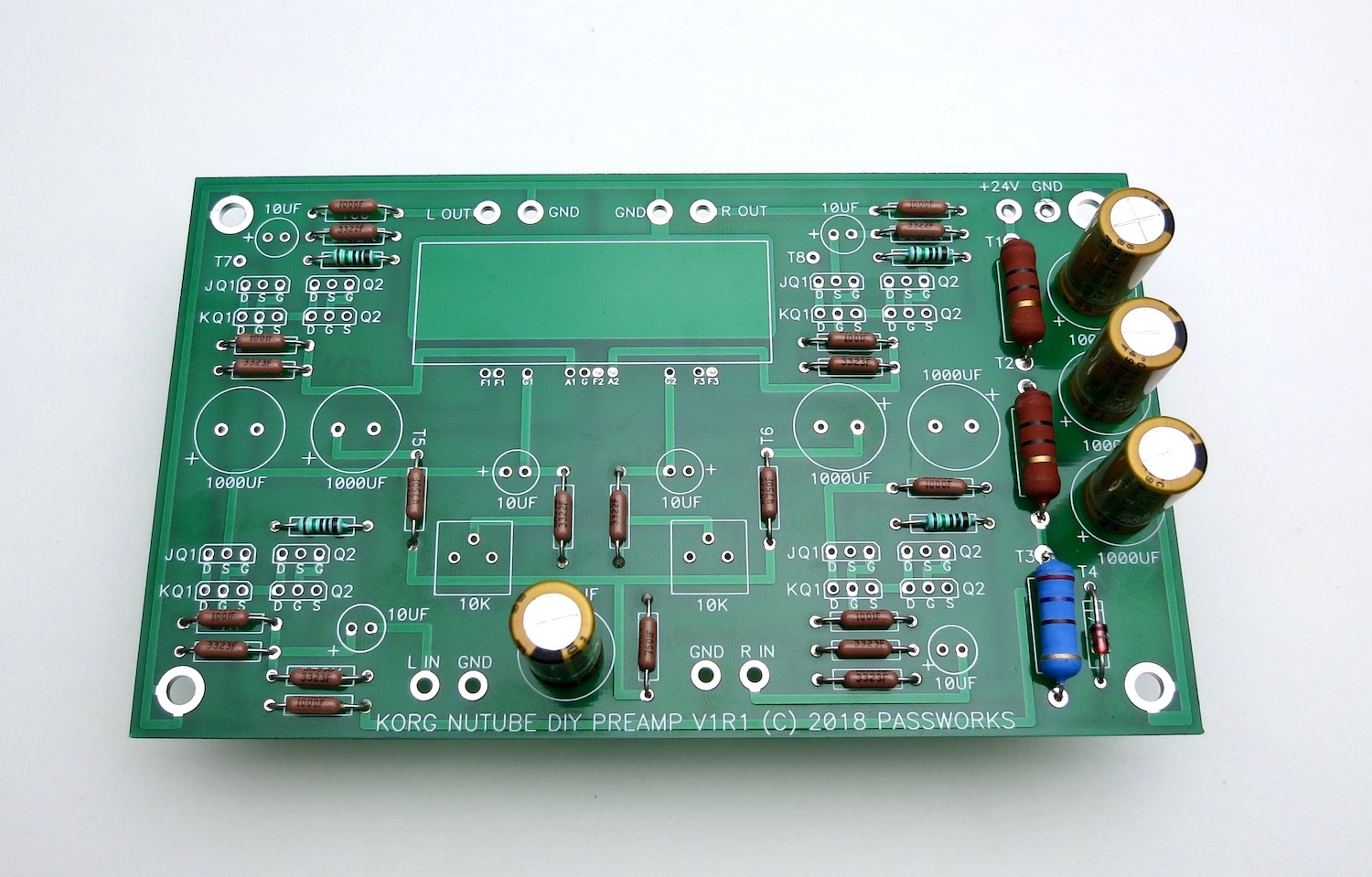
Stuff all the resistors. The value is printed not he PCB except for the "R1" positions.
Neatness counts.
Bend all the leads so the value is on top and readable.
Insert them into the PCB so the values read left to right or bottom to top. (On the R1s, put the thicker brown band to the right)
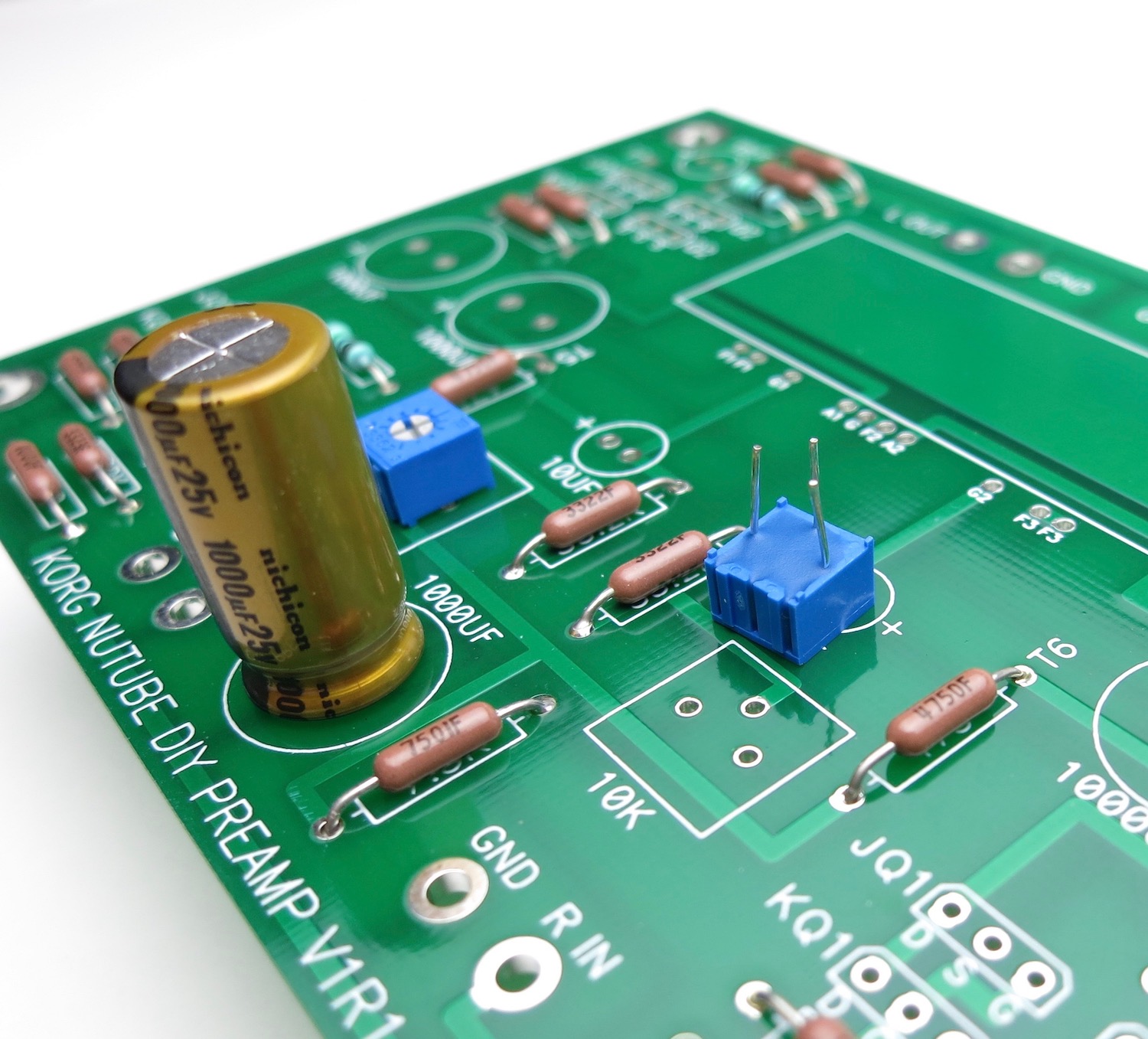
Trimmer potentiometers
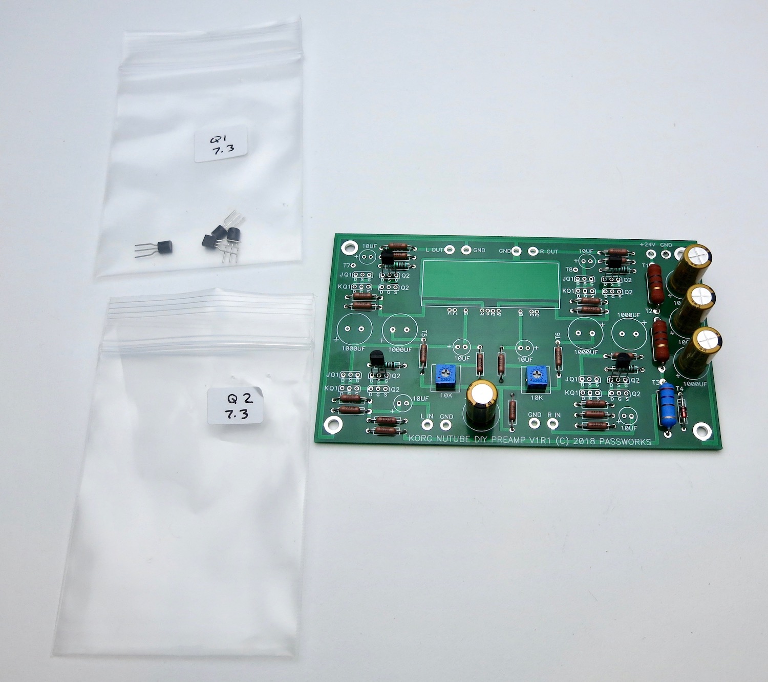
There are two rows in each position for Jfets, one marked "JQ1 Q2" the other marked "KQ1 Q2"
…These boards will allow the use of different JFETs. If you purchased the full kit, ONLY stuff the locations marked with J.
The rows with the J are for the J113 parts (Fairchild, included in the kits)
The rows with K are for K170 parts (Toshiba, not included)
Only use one or the other! You don't need to use both rows.
Open one bag at a time so you don't mix them up. 🙂
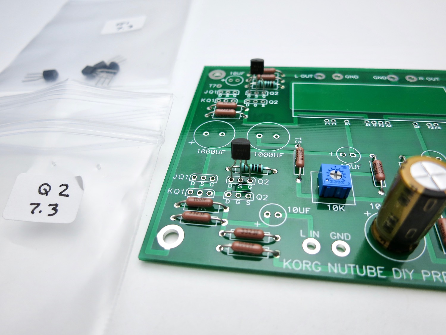
Kit parts use the "J" row
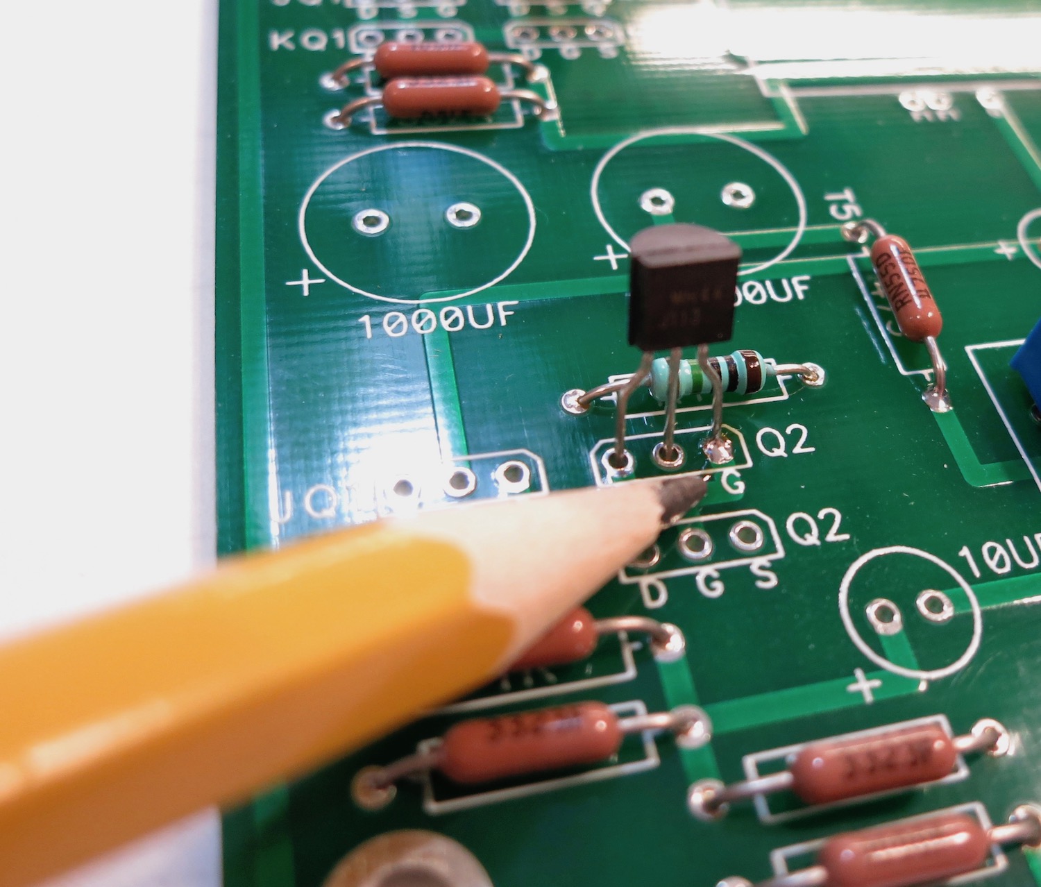
You can solder one leg from the top to keep them in place when you solder the bottom.
Stuff the other bag
Jfets complete
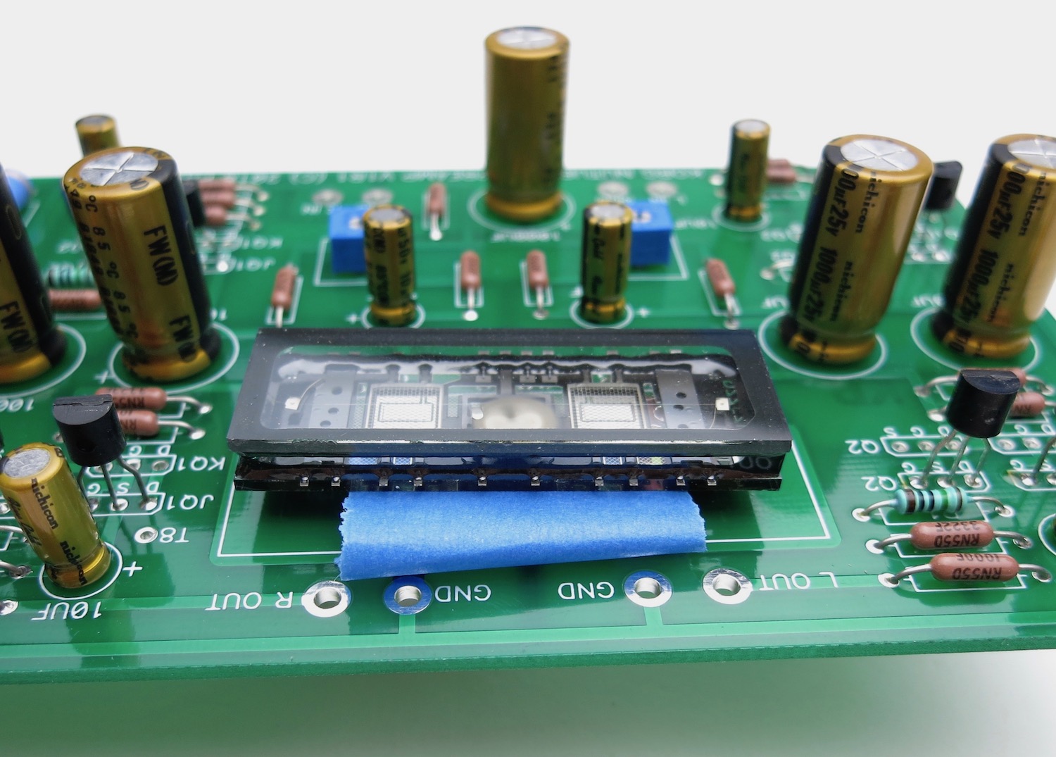
NuTube is next. Make a loop of tape under the NuTube to make some room above the PCB, you don't want it to touch. Solder the pins
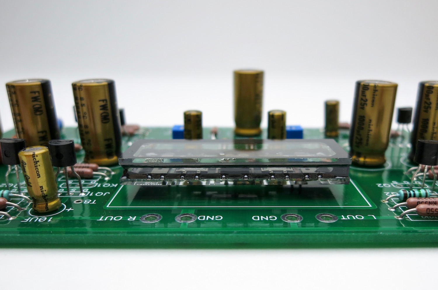
Let it float above the board
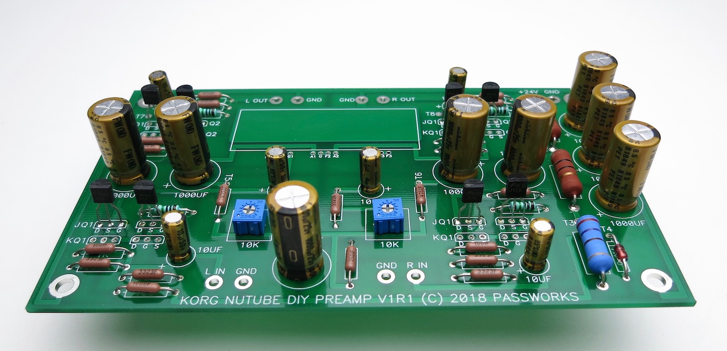
Fully stuffed PCB
The PCB kit comes with two bags and resistors, don't mix them up, and don't lose the resistors, as they are selected for those specific transistors, in your kit.
The resistors go into the spot marked "R1" on the PCB, there are (4) places. These locations have no value printed on them nor does the schematic have a value. They are selected to mate with the included transistors.
Gather the rest of the PCB parts
As mentioned earlier, the resistors are all on 0.5" lead spacing
The Dale resistors have their value marked in digits on the side
This is 3-digit+multiplier
The top resistor is 100 ohms -- 100+0, or "one hundred ohms and zero zeroes"
The bottom is 1K -- 100+1, "one hundred and one zero"
Top 33.2K "332 + two zeroes"
Bottom 332K "332 + three zeroes"
Stuff all the resistors. The value is printed not he PCB except for the "R1" positions.
Neatness counts.
Bend all the leads so the value is on top and readable.
Insert them into the PCB so the values read left to right or bottom to top. (On the R1s, put the thicker brown band to the right)
Trimmer potentiometers
There are two rows in each position for Jfets, one marked "JQ1 Q2" the other marked "KQ1 Q2"
…These boards will allow the use of different JFETs. If you purchased the full kit, ONLY stuff the locations marked with J.
The rows with the J are for the J113 parts (Fairchild, included in the kits)
The rows with K are for K170 parts (Toshiba, not included)
Only use one or the other! You don't need to use both rows.
Open one bag at a time so you don't mix them up. 🙂
Kit parts use the "J" row
You can solder one leg from the top to keep them in place when you solder the bottom.
Stuff the other bag
Jfets complete
NuTube is next. Make a loop of tape under the NuTube to make some room above the PCB, you don't want it to touch. Solder the pins
Let it float above the board
Fully stuffed PCB
Last edited:
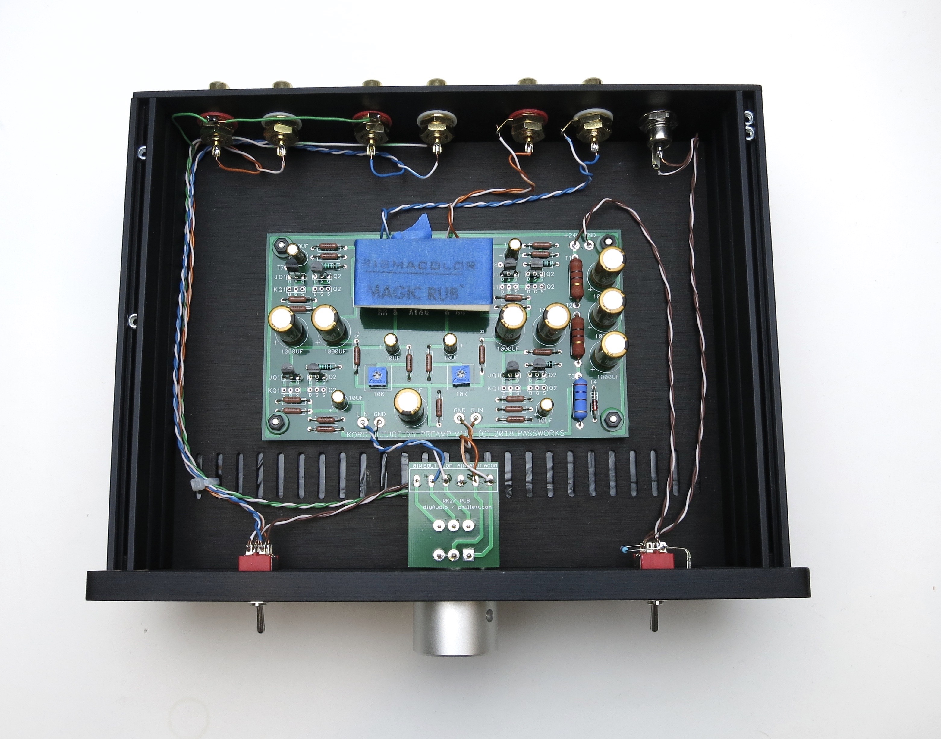
The standoffs attach to the inside of the bottom panel.
Attach wires from potentiometer to Korg PCB
Blue and white/blue for Left.
Orange and white/orange for Right.
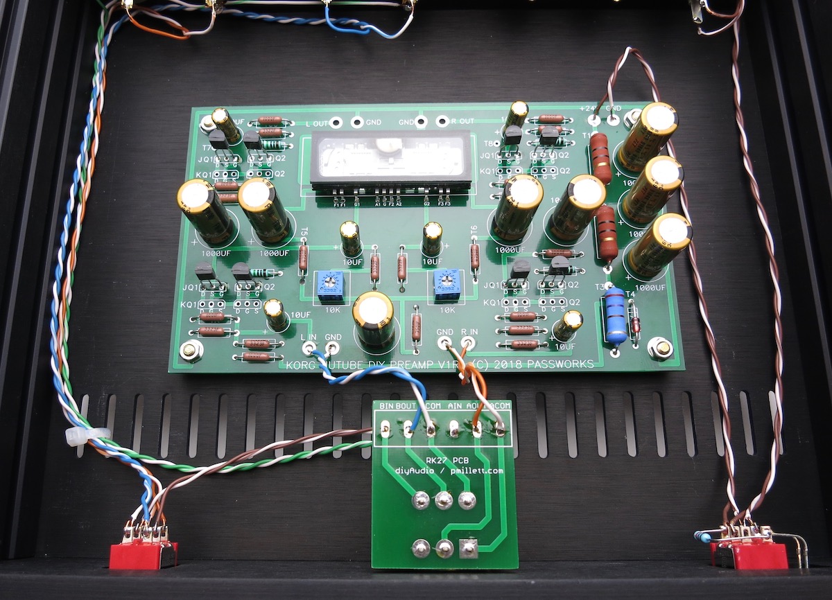
Attach output RCAs as shown. We will use the same colors as the short leads from the pot board to the main PCB.
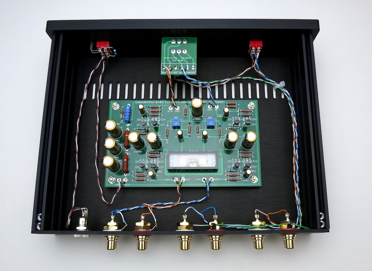
Completed internal assembly.
Attach knob.

Last edited:
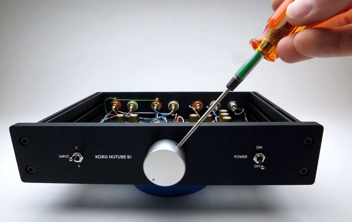
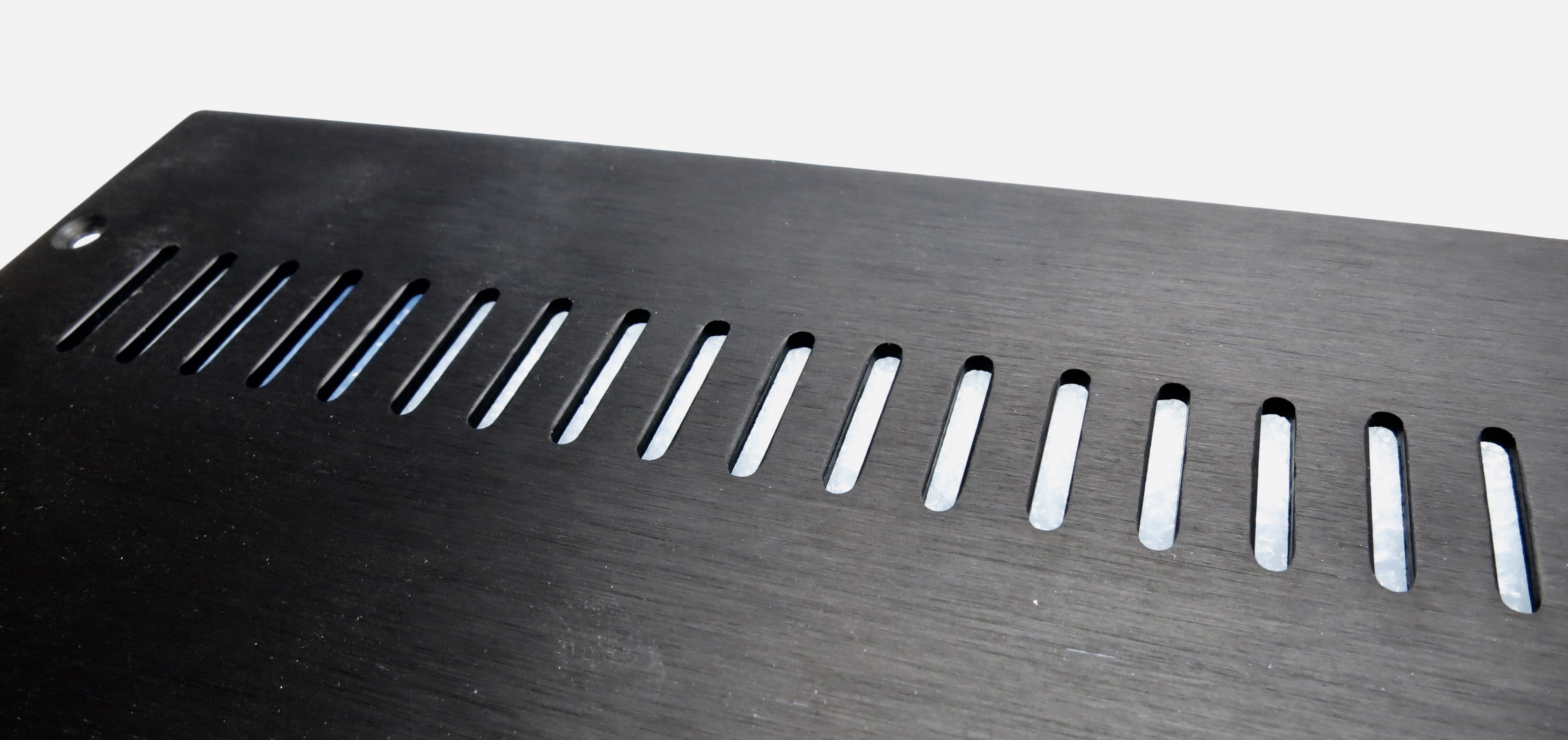
FIGHTING MICROPHONICS
The Nutube can be microphonic. Everybody will hear it when they flip a switch, but some of the Nutube themselves are worse than others, it seems to be the vagaries of production. I tried a number of different solutions and the best results were to take a white latex pencil eraser to the to top of the glass, and then seal up the vent holes in the chassis. Newer chassis will not have vent holes.
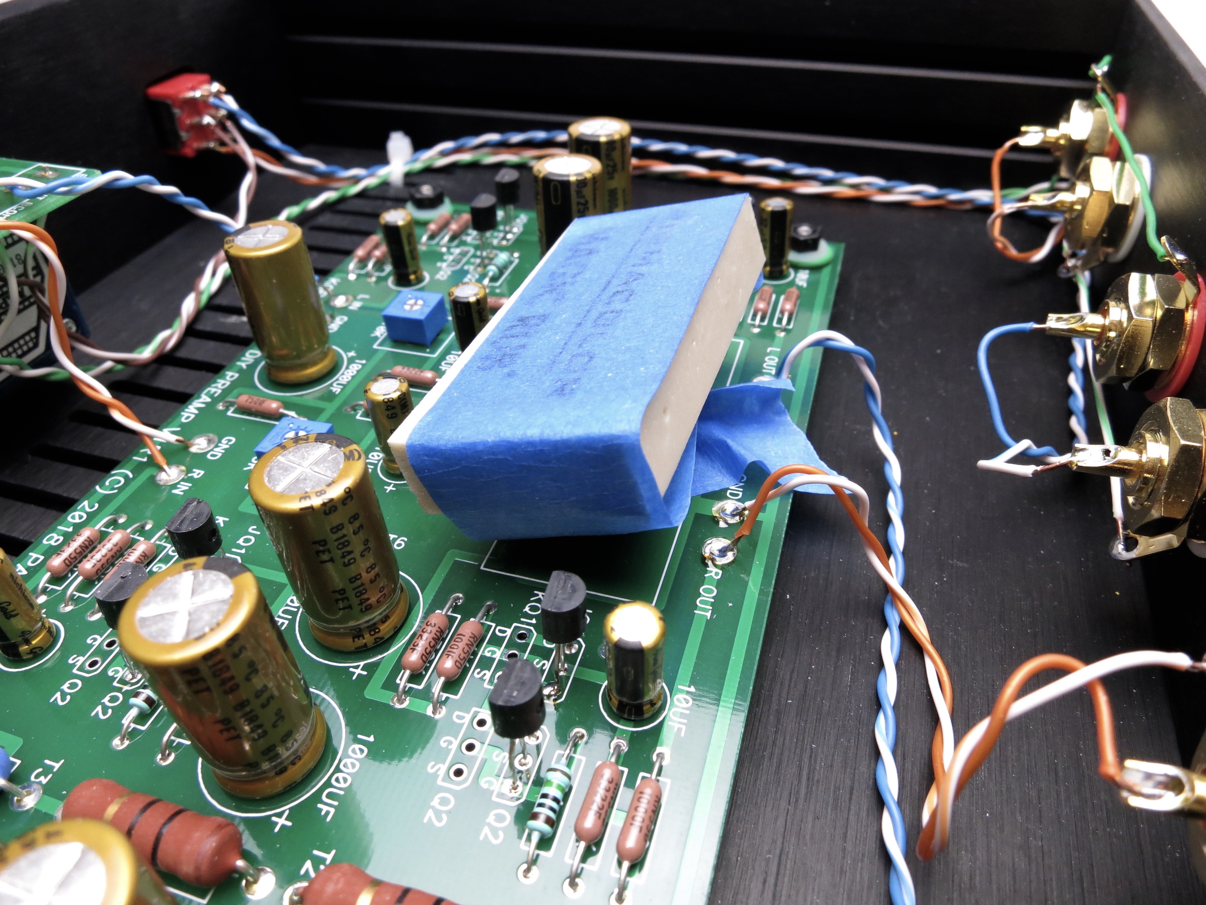
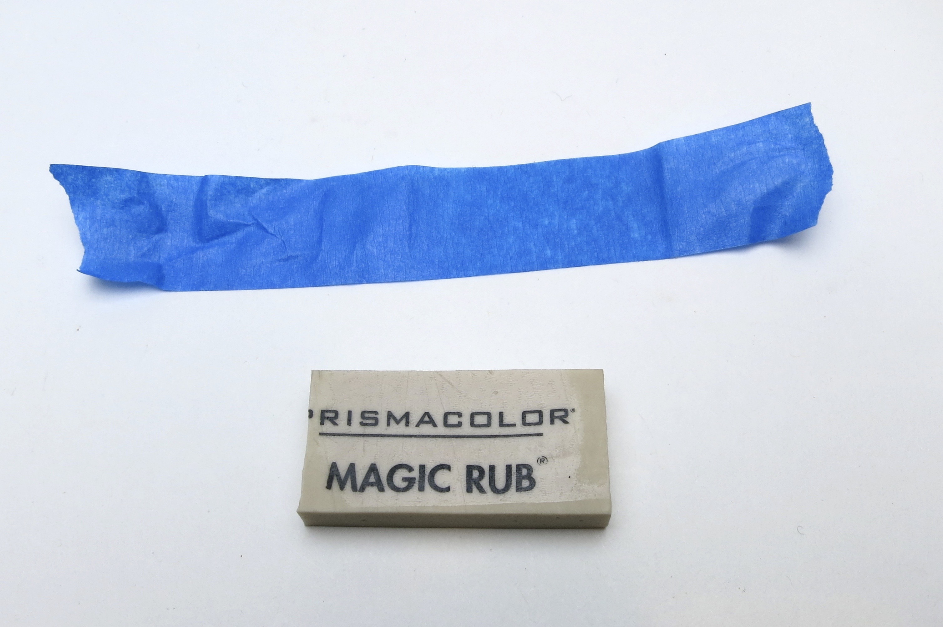
Eraser trimmed to width. Taping it in place seems to damp better than something sticking directly on the surface. (Yes, it is counterintuitive...)
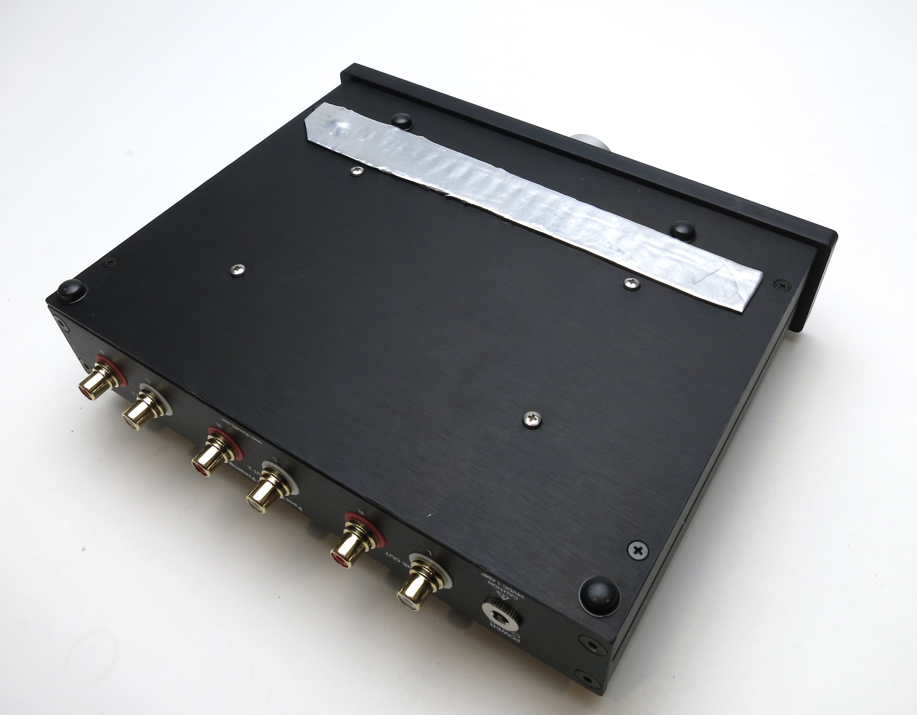
This is a self-adhesive rubberized material similar to Dynamat.
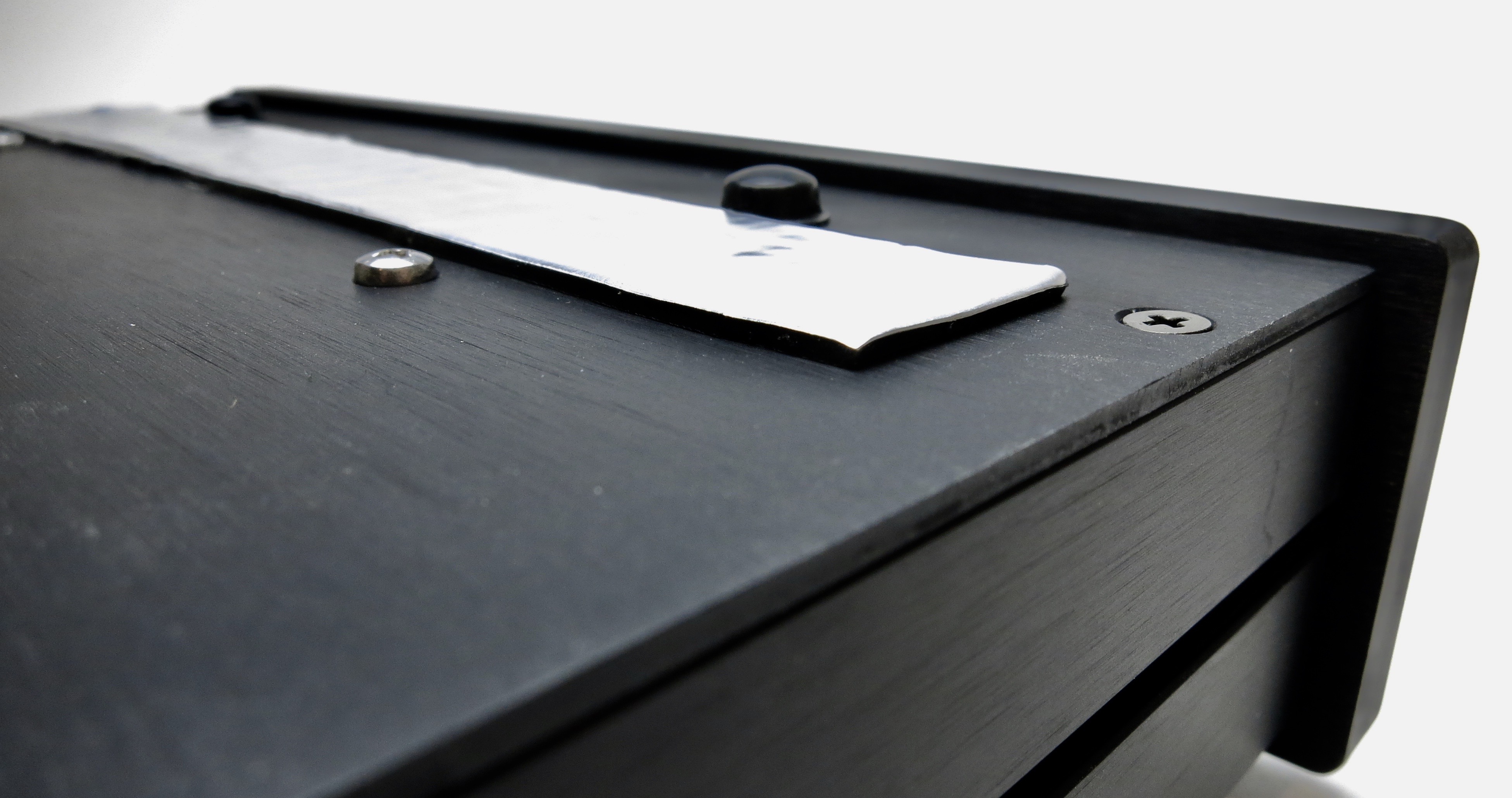
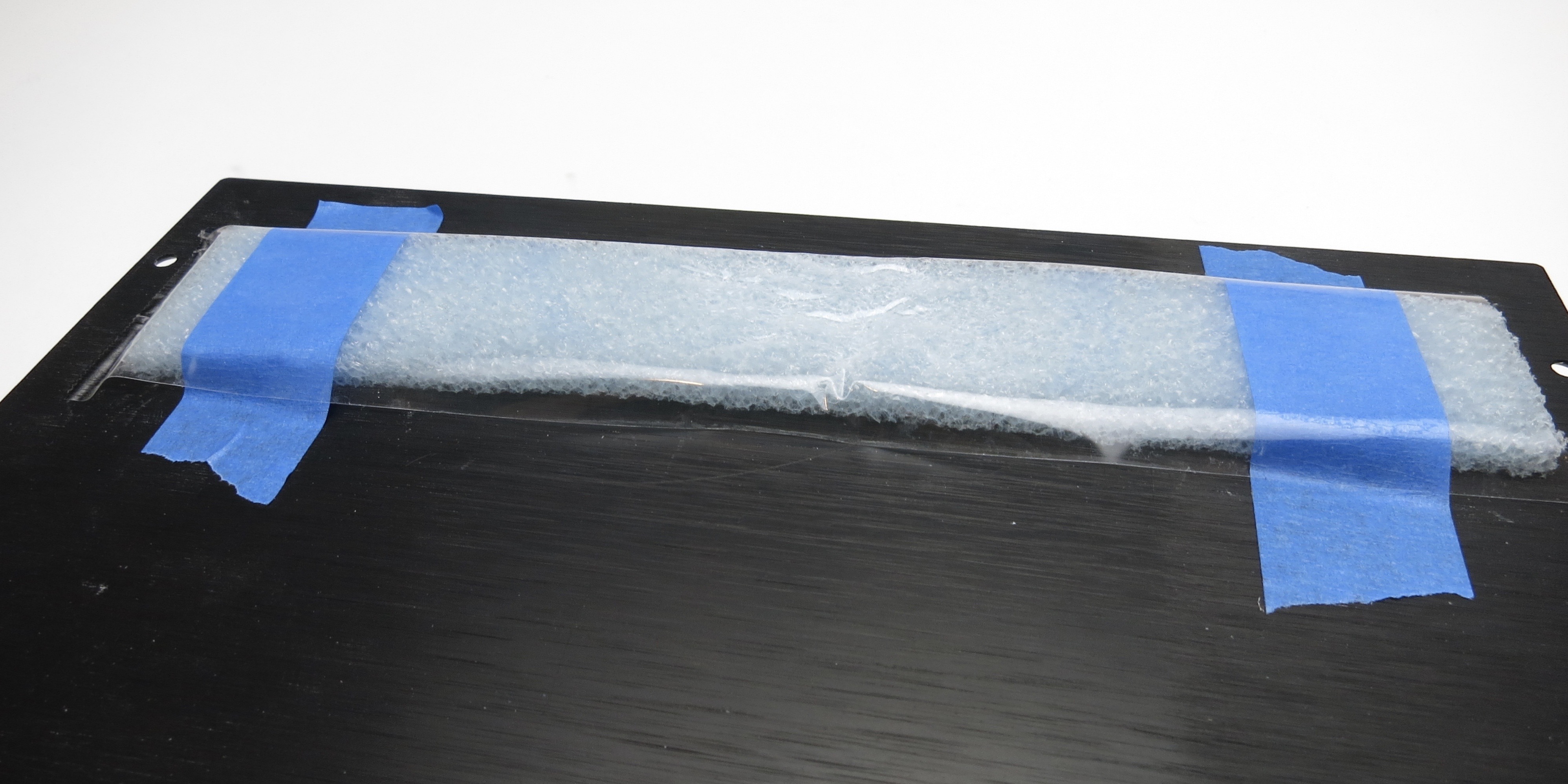
This is just some closed-cell shipping foam taped to the inside of the vents. Both it and the sticky foil-backed material worked well. Blocking it seems to be more important than absorbing or damping.
If anybody has suggestions or examples of what works, please share them! 🙂
The Nutube can be microphonic. Everybody will hear it when they flip a switch, but some of the Nutube themselves are worse than others, it seems to be the vagaries of production. I tried a number of different solutions and the best results were to take a white latex pencil eraser to the to top of the glass, and then seal up the vent holes in the chassis. Newer chassis will not have vent holes.
Eraser trimmed to width. Taping it in place seems to damp better than something sticking directly on the surface. (Yes, it is counterintuitive...)
This is a self-adhesive rubberized material similar to Dynamat.
This is just some closed-cell shipping foam taped to the inside of the vents. Both it and the sticky foil-backed material worked well. Blocking it seems to be more important than absorbing or damping.
If anybody has suggestions or examples of what works, please share them! 🙂
Last edited:
The final public version of this guide has now been published at:
B1 with Korg Nutube - diyAudio Guides
This thread will now be closed. Please post any questions in the main B1K thread.
B1 with Korg Nutube - diyAudio Guides
This thread will now be closed. Please post any questions in the main B1K thread.
- Status
- Not open for further replies.
- Home
- Amplifiers
- Pass Labs
- Korg NuTube B1 guide