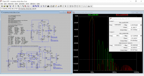
I put the recommended analysis parameters in the file to see how low we could go. As we go lower in distortion, the tap point for the difference amplifier starts to matter. Taking the tap from the mid point of the drivers or the bias network starts to introduce some potentially variable impedance, so I moved it directly to the output of the difference amplifier. This adds to the DC offset the difference amplifier needs to make up. The impedance of the voltage source used to offset starts to matter, and we don't have a lot of power or parts count for a super low impedance regulator, so I used two current sources to add a DC offset without upsetting the impedance balance. With these changes, I was able to get the opamp error corrector to about -140dB at 10V into 8Ohms at 100Hz, or -120dB at at 10W into 4Ohms at 1kHz (attached). I think this may be close to achievable because the dominant difference amplifier impedances are now well controlled, and the opamp distortion feeds through at a small fraction because it only sees the error signal.
As LKA suggested, keeping the impedance under control through high frequencies seems important to avoid out of band oscillation. But, if we bypass the error corrector with a resistor and capacitor to maintain low impedance at high frequencies, we can get some peaking for the opamp feedback circuit that could boost the loop gain close to 1 where it should be turning off. I tuned some values to get this under control with my model, but it seems it might need to be tuned after building.
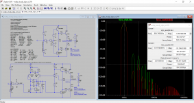
I compared the updated opamp and updated discrete version of the error corrector circuit to a standard emitter follower. I upped the stakes, and biased the standard EF circuit into push pull class A. The error corrector circuits are still class B. At this point, I am not sure which error corrector I will build, but I am leaning toward the discrete one because I think I have a handle on the high frequency model being accurate. My simulations for the discrete one show about the same performance as LKA's, and about the same voltage overhead needed. The main point I was going for in this implementation approach versus Hawkford's is to leave my existing bias network and amplifier alone by placing the error corrector in series. This one also has a nice property that the error signals produce self-cancelling currents so they don't get passed to the VAS.
As LKA suggested, keeping the impedance under control through high frequencies seems important to avoid out of band oscillation. But, if we bypass the error corrector with a resistor and capacitor to maintain low impedance at high frequencies, we can get some peaking for the opamp feedback circuit that could boost the loop gain close to 1 where it should be turning off. I tuned some values to get this under control with my model, but it seems it might need to be tuned after building.
I compared the updated opamp and updated discrete version of the error corrector circuit to a standard emitter follower. I upped the stakes, and biased the standard EF circuit into push pull class A. The error corrector circuits are still class B. At this point, I am not sure which error corrector I will build, but I am leaning toward the discrete one because I think I have a handle on the high frequency model being accurate. My simulations for the discrete one show about the same performance as LKA's, and about the same voltage overhead needed. The main point I was going for in this implementation approach versus Hawkford's is to leave my existing bias network and amplifier alone by placing the error corrector in series. This one also has a nice property that the error signals produce self-cancelling currents so they don't get passed to the VAS.
Attachments
That illustrates the basic difference between negative feedback and error correction. The limiting factor with negative feedback, to get lower distortion, is how large you can make the loop gain while maintaining stability.
The limiting factor with error correction is how accurate you can make the derivation and subsequent summing of the error signal with the main signal.
And, what stays mostly undetected, is the bandwidth required for accurate error correction. For instance, if you want to correct the error at 10kHz to 0.1%, your error correction circuit needs a bandwidth of 1000 * 10kHz or 10MHz.
Jan
This scheme is not true error correction: it relies on local feedback rather than global feedback, and the comparator input is (very slightly) unusual, but in the end it boils down to NFB like 99% of so-called "-EC" schemes, and it is subject to the same limitations and constraints: make the gain of the gain cell zero, and nothing will happen, make it infinite and it will oscillate like mad.
Calling it EC obscures the needs for loop gain and stability, and is thus not helpful.
Predistortion for example is an example of basic, but true EC, and its effectiveness will depend on the accuracy of the predistortion.
More elaborate forms are parametric error correction: if Mazurek dynamically modulated the Vbe spreader to correct the errors, this would count as EC, even if there is a return feedback path, because the FB path cannot directly generate a signal by itself: it simply modulates the "noble" path

O.k. that’s interesting information, I’ll give it a try, thanks.Hans, those equations are meant to obtain max FFT resolution and lowest noise floor. They make sure that the FFT is synchronous with the signal, so that there is no spectral leakage without a window. Also the time step is set so that it is the exact value required by the synchronous FFT. The FFT value defined (like 10^19) gives also the value to set the FFT length to in the View|FFT window.
This is independent from numdgt and waveform compression. It is very similar to what you would do in ARTA or REW for max resolution, synchronous FFT.
The numcyc, numdly etc are not required for the FFT but set the simulation length and data collection length based on frequency for a nice 3-cycle display.
Jan
Hans
Calling it EC obscures the needs for loop gain and stability, and is thus not helpful.
Jan's earlier comment also had me thinking about the benefit of "error correction" relative to traditional feedback ... and I came up empty. A feedback only circuit of a similar architecture is attached with the same loop gain and fewer parts, and is my favorite.
I was wondering if there are any tangential reasons that make these different from each-other, but the eigenvalues and their stability must be the same because the transfer function is the same. Maybe one clips more elegantly, or maybe they are the same and simply a nicely stabilizing feedback term because they have a wide bandwidth with 90 degrees phase where other feedback terms are usually added in.
A limiter is needed between the inputs of the correction OPamp. Usually included diodes.
Thanks, OLDDiy, I know the opamp has built in diodes, but I forgot them on my long tailed pair concept. I believe the presently attached single ended version is safe from VBE reverse bias, but let me know if you think otherwise.
WW1975 (AKSA)
Thank you for reading my intent. This investigation started for me by being frustrated that the Quad or CFP outputs are nicely linearized when they are on but not for the transition, and it seems one should be able to wrap the CFP feedback around the whole stage to eliminate crossover distortion. Your latest reply looks like another great way of wrapping complementary feedback around the output stage. I considered some architectures where a driver transistor is inverting so we can use it as a gain element and was wondering if there are drawbacks due to the driver doing double duty of serving as a local VAS stage as well as supplying current to each output transistor. But it must be ok, I've seen some opamp datasheets like this one.
I am liking the floating negative feedback concept better than the "error correcting" circuit with positive and negative feedback. One issue I had with arrangements with intermediate gain or buffers referenced to the rails isthat they can dump a lot of current into the driver or its buffer, and if one uses that current to limit the main VAS to prevent destruction, there can be too much phase shift due to the added intermediate stages so that clipping and current limiting can cause it to temporarily oscillate. I like the floating corrector partly because it disappears at high frequencies and does not seem to have a major impact on open loop bandwidth.
Attachments

Just in case people thought I was done reinventing the wheel, in the last post after I deleted the long tailed pair from the discrete "error corrector" and replaced it with a simple resistor to negative feedback, it became .... a shunt voltage regulator. Still I think it might be useful as a method for output stage linearization.
Local feedback can undoubtedly be useful, but it shouldn't be confused with error correction.
The very general principles show that a big GNFB loop is always superior to a number of smaller, local loops, but using a large juggernaut like GNFB to iron out tiny local wrinkles is extremely demanding, sometimes altogether impossible from a practical POV.
Applying GNFB to a collection of well-behaved, locally linearized function-blocks therefore makes sense.
That is something I don't dispute.
These local correction loops look very much like error correction -but they aren't-.
The distinction is essential, because the behavior is essentially different: if you think you can dispense with control theory with local feedback circuits, they will come back and bite you in some way, and if you design real EC circuits like FB ones, you won't be able to use their full potential.
Predistortion is the simplest, true EC scheme, but there are other, more elaborate ones: the seminal cross-quad of course, its variations like the Evaquad, and other varieties like the unigabuf, the tringlotron, etc
Here is one more concept that compares Hawksford/Kolinummi/LKA's circuits that technically have both negative and positive feedback to a similar looking one with only negative feedback. First, a taxonomy discussion, then performance.
TAXONOMY
Its difficult to be respectful to the source material without using the words "error correction", and I think that's why some use the term feedback error correction which is also a bit confusing. This thread hasn't really focused on true error correction so far, but Hawksford's so called "error correction feedback system" (and Cordell/Kalinummi/etc updates) that is really a mixture of positive and negative feedback. One of the highlights of his paper is that it is a net negative feedback system that directly feeds back on the error part which might give some kind of dynamic range benefit.
Thank you for providing some searchable terms for true EC schemes. Douglas Self's Audio Power Amplifier Design book compares a basic long tailed pair to one with cross quad error correction, and one with local feedback in the form of the CFP or Sziklai pair. Unfortunately the cross quad method modified the impedance of his circuit in a way that made it difficult to stably measure even though it is supposed to be a feedforward method, but the CFP with local feedback nicely improved performance with no major architecture changes (I am guessing because the emitter degeneration covers up any reactive impedance due to the local feedback). The difficulty is in the details, but I understand the idea that true EC is an attractive way to narrow the distortion spectrum without creating new harmonics, versus superimpose a harmonic multiple to cancel the sins of the first harmonic.
So in conclusion, I am now labeling the compared concepts negative feedback versus positive and negative feedback.
PERFORMANCE
This current post asks whether there are any negative feedback only (what I meant in the previous post by traditional feedback) architectures that have the same benefit as for example LKA's implementation of the Hawksford concept. I redrew the previous voltage reference concept to be differential so it now looks like LKA's circuit but isn't. The major difference is that it only uses inverting feedback and no positive feedback, and practically this current circuit looks a lot like a dual VAS amplifier.
I would say the performance and parts count is pretty good, and because it is floating it also works on a reduced dynamic range, just like Hawksford's concept. I am betting you could cast all these as equivalent by changing the reference frame, but the practical implementation matters. The positive feedback in Hawksford's concept brings about an impedance balancing requirement that can limit performance. However, the floating negative feedback only approach has no such requirement. Ultimately, I am not sure whether the positive feedback resulting from so called "error correction feedback" really serves a purpose relative to a similar circuit with the same effective negative feedback. I am wondering whether there are any real sensitivity differences to model changes or such.
Luckily, as OLDDiy's posts show, we seem to have a number of useful methods to choose from for reducing crossover distortion, and LKA showed with measured data that they can yield impressive gains on their amplifier by nesting this style of wide bandwidth local feedback with the output.
So in conclusion, I showed some reasonable negative feedback only options (last post, this post) to glue into a blameless type architecture, and in simulation it has about the same benefit as previously published methods.
*For those not counting, there are at least two puns "sins (=sines) of the first harmonic", and "impressive gains (=linear voltage gain) on their amplifier".
TAXONOMY
Local feedback can undoubtedly be useful, but it shouldn't be confused with error correction.
Its difficult to be respectful to the source material without using the words "error correction", and I think that's why some use the term feedback error correction which is also a bit confusing. This thread hasn't really focused on true error correction so far, but Hawksford's so called "error correction feedback system" (and Cordell/Kalinummi/etc updates) that is really a mixture of positive and negative feedback. One of the highlights of his paper is that it is a net negative feedback system that directly feeds back on the error part which might give some kind of dynamic range benefit.
Thank you for providing some searchable terms for true EC schemes. Douglas Self's Audio Power Amplifier Design book compares a basic long tailed pair to one with cross quad error correction, and one with local feedback in the form of the CFP or Sziklai pair. Unfortunately the cross quad method modified the impedance of his circuit in a way that made it difficult to stably measure even though it is supposed to be a feedforward method, but the CFP with local feedback nicely improved performance with no major architecture changes (I am guessing because the emitter degeneration covers up any reactive impedance due to the local feedback). The difficulty is in the details, but I understand the idea that true EC is an attractive way to narrow the distortion spectrum without creating new harmonics, versus superimpose a harmonic multiple to cancel the sins of the first harmonic.
So in conclusion, I am now labeling the compared concepts negative feedback versus positive and negative feedback.
PERFORMANCE
This current post asks whether there are any negative feedback only (what I meant in the previous post by traditional feedback) architectures that have the same benefit as for example LKA's implementation of the Hawksford concept. I redrew the previous voltage reference concept to be differential so it now looks like LKA's circuit but isn't. The major difference is that it only uses inverting feedback and no positive feedback, and practically this current circuit looks a lot like a dual VAS amplifier.
I would say the performance and parts count is pretty good, and because it is floating it also works on a reduced dynamic range, just like Hawksford's concept. I am betting you could cast all these as equivalent by changing the reference frame, but the practical implementation matters. The positive feedback in Hawksford's concept brings about an impedance balancing requirement that can limit performance. However, the floating negative feedback only approach has no such requirement. Ultimately, I am not sure whether the positive feedback resulting from so called "error correction feedback" really serves a purpose relative to a similar circuit with the same effective negative feedback. I am wondering whether there are any real sensitivity differences to model changes or such.
Luckily, as OLDDiy's posts show, we seem to have a number of useful methods to choose from for reducing crossover distortion, and LKA showed with measured data that they can yield impressive gains on their amplifier by nesting this style of wide bandwidth local feedback with the output.
So in conclusion, I showed some reasonable negative feedback only options (last post, this post) to glue into a blameless type architecture, and in simulation it has about the same benefit as previously published methods.
*For those not counting, there are at least two puns "sins (=sines) of the first harmonic", and "impressive gains (=linear voltage gain) on their amplifier".
Attachments
Last edited:
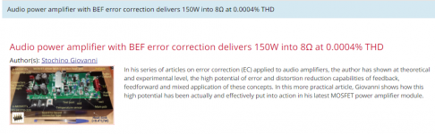
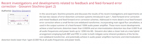
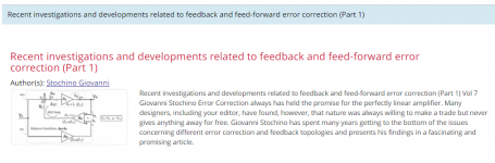
There's is another universum of detailed worked out error correction concepts from Giovanni Stochino. Very extensive calculations, simulations and measurements.
This is more like the standard material on this.
He has several articles written for Linear Audio at the time:
Volumes 7, 8, 9, 11, 13.
volumes | Linear Audio
Jan
This is more like the standard material on this.
He has several articles written for Linear Audio at the time:
Volumes 7, 8, 9, 11, 13.
volumes | Linear Audio
Jan
Attachments
I have a big power amp using ‘augmented feedback error correction’ (AFEC) that gives about 20 dB distortion reduction. Here are some notes on the technique. Easy to implement but you do need a trim pot to null the distortion. The resultant compensation scheme is TPC.
Augmented Feedback Error Correction (AFEC)
Augmented Feedback Error Correction (AFEC)
Yes I know that design - very worthwhile reading the article!
BTW Your link in the ref section to may paX error-correction power amp design seems in error, should be paX - an error-correction power amp | Linear Audio NL ;-)
Jan
BTW Your link in the ref section to may paX error-correction power amp design seems in error, should be paX - an error-correction power amp | Linear Audio NL ;-)
Jan
Negative feedback reduces gain and as a byproduct reduces distortion. Positive feedback increases gain. EC does not primarily change gain although it must change gain by small amounts in order to perform its function. However, 20dB EC distortion reduction is not achieved with the commensurate change of gain. So is labeling it negative and positive feedback applicable?
The type of feedback is not defined by what it does to the gain. It is defined by the phase of the signal that it feeds back.
Jan
Jan
AFEC is definitely a feedback type of error reduction. You do have to null it because the resistor tolerances in the bridge formed by the two feedback networks is about 2% worst case.
Here is a comparison of two schematics that accomplish similar objectives of disturbance rejection and unity gain output, one by conventional feedback, one by Hawksford EC according to my best trimming and phase matching. The major way they differ for my drawing is in what gets fed back to the '+' LTP node.
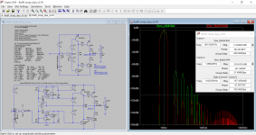
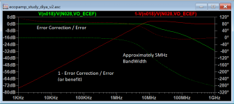
First plot is my cartoon of Jan's comment on phase matching concept. It is created by injecting a current disturbance into the output and, and it shows a green line which is the transfer function between error and modified command or correction signal. This goes to unity at low frequencies due to gain trimming and phase matching. The red line is 1-command/error and that is the linear performance benefit.
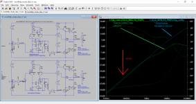
The second plot is this the performance benefit part of the error correction cartoon for a circuit designed with Hawksford error correction philosophy, and one designed with feedback disturbance rejection philosophy. They are pretty similar at low frequencies and diverge at high frequencies.
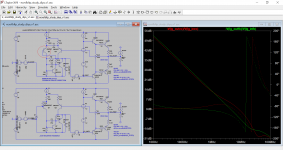
The last plot shows the resulting loop gain for each philosophy by making a voltage injection at the driver command point for each. Again, they are pretty similar. There is a little red circle to highlight the '+' node on the LTP.
But ultimately I am getting to the point of too much analysis and not enough building, so I need to catch up to these other fellows who have realized truly excellent performance in the work they built and referenced.
First plot is my cartoon of Jan's comment on phase matching concept. It is created by injecting a current disturbance into the output and, and it shows a green line which is the transfer function between error and modified command or correction signal. This goes to unity at low frequencies due to gain trimming and phase matching. The red line is 1-command/error and that is the linear performance benefit.
The second plot is this the performance benefit part of the error correction cartoon for a circuit designed with Hawksford error correction philosophy, and one designed with feedback disturbance rejection philosophy. They are pretty similar at low frequencies and diverge at high frequencies.
The last plot shows the resulting loop gain for each philosophy by making a voltage injection at the driver command point for each. Again, they are pretty similar. There is a little red circle to highlight the '+' node on the LTP.
But ultimately I am getting to the point of too much analysis and not enough building, so I need to catch up to these other fellows who have realized truly excellent performance in the work they built and referenced.
Attachments
There's is another universum of detailed worked out error correction concepts from Giovanni Stochino.
Thank you so much to Jan and others with helping me organize a reading list to get up to speed.
- Home
- Amplifiers
- Solid State
- Kolinummi concept for reducing crossover distortion implemented on Blameless