I recently realized I effed up and reversed the screen and suppressor on a PCB for 6P45S.
The thing is though, isn't it a beam tube? I know I'd still have a triode if I tied suppressor to plate instead of cathode, and in the past when I push things like this, I'm worried about something burning out, but this is a beam forming plate, no? In theory it should not only work well as a triode but handle extra Pd since it's a plate not a wire?
I don't want to waste a pair of 6P45S trying this before some other people think I'm sane here. I've already had one tube plate cap come off, and another roll off of the table and smash...
Worst case? In a week the corrected boards will come.
The screen grid can handle a few Watts so can the suppressor screen but not more then 5 Watt maybe. If the Anode is connected together with the suppressor then this will be fine but never remove the anode and let the suppressor do the job (only if you adjust the current to a max of 5W)!
You also can disconnect both the anode and suppressor and use the screen as anode (also reduce the current to max 5W)
Ya thanks, but not helpful.
Plate, suppressor, screen connected on 6P45S vs Suppressor tied to cathode. Did you measure the difference in triode? Your example says maybe suppressor is worth 5W... That makes a total of almost 50W, so what? Does it change the bias point?
Plate, suppressor, screen connected on 6P45S vs Suppressor tied to cathode. Did you measure the difference in triode? Your example says maybe suppressor is worth 5W... That makes a total of almost 50W, so what? Does it change the bias point?
Last edited:
Suppressor Grids are actual Grids.
They are only present on real Pentodes (EL34, EL84, 6AU6, etc.).
Beam Formers are actual sheet metal.
They are only present on real Beam Power tubes (807, KT66, 7591, etc.).
The only time I remember Both the screen grid and the suppressor grid were tied to the plate was the EL34 Randall Museum group build project amplifier in San Francisco at least a couple of decades ago.
I recommend using the beam formers as what they were intended to do . . .
When connected to the cathode, they form a Beam to the intended sides of the plate, and they also can attract secondary emission electrons that come off the plate.
And, for Pentodes, I recommend connecting the Suppressor screen to the cathode, to do what they were intended to do, collect (suppress) the secondary electrons that come off the plate.
YMMV . . . Your Mileage May Vary.
Just my opinions.
Last edited:
Ya thanks, dude!. Still... Are 6P45S beam tubes or with suppressors? Never seen a tube with both,
If they were tied to plate that makes the plate bigger? More Pd?
If they were tied to plate that makes the plate bigger? More Pd?
I use ghostery and other ad blockers and I think I have cross posted maybe 3 times in the 17 years I have been here. Almost no one else complains about this, so maybe the problem is with you?
Your language violates forum rules, and is not necessary.
I'll remove the cross posts.

Your language violates forum rules, and is not necessary.
I'll remove the cross posts.
The 6P45S is often promoted as equal to some other types.
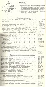
If I look at pictures of a 6P45S (I see marking of 6P45C), I can see the shiny colored Beam Former sheet metal that is visible behind the holes of the grey/black plates. And you have those tubes, so you can see that too.
That is a real Beam Power tube, sometimes called a Beam Tetrode.
The 6P45s (or C), does not have a Suppressor grid.
I doubt that any production tube has both a suppressor grid, and a beam former.
Well, there is a special tube with two Deflection sheets, it might also have a suppressor grid.
But the beam formers are two, with two separate connections, and they deflect the electrons from one side to the other.
But Beam Power tubes beam formers are connected together, not separately.
There are 'Bird Cage' Tetrodes, also called Beam Tetrodes, which do not have a suppressor grid, and do not have Beam Former sheet metal.
4X150, 4-65A, etc.
The beam forming is because both the control grid, and the screen grid are bird cages, with equal number of wires, and are rotationally aligned so the plate can "see" through the screen grid and control grid all the way back to the cathode.
Confusing?
Yes.
Nomenclature gets abused.
Last edited:
I recommend using the beam formers as what they were intended to do . . .
When connected to the cathode, they form a Beam to the intended sides of the plate, and they also can attract secondary emission electrons that come off the plate.
True, but doesn't answer the OP's question. I am curious also. If you operate a beam tube in triode, is there any harm in connecting the beam plate to the anode, together with G2?
The 6KG6 data sheet says beam plate Vmax=50V, but I'm not sure why or how that would play in triode.
When you connect anode, g2 and g3/beamplates all together, I don't see why you should worry about the max voltage of g3/bp as it is sandwiched between elements with the same potential. You have to be carefull anyways with the max B+ to prevent runaway conditions as Tubelab George found running big TV tubes in SET. Still fine quite higher than max g2 according to the datasheets (pentode mode).
The effect on the curves can be seen in an example on page 22 (small signal pentode EF91):
http://www.audiodesignguide.com/New2A3/ETF06TS.pdf
The effect on the curves can be seen in an example on page 22 (small signal pentode EF91):
http://www.audiodesignguide.com/New2A3/ETF06TS.pdf
Measure the current and see. It can probably dissipate more than the screen, but obviously much less than the plate.
It may or may not be pertinent to discussion:
I have done as you describe Koda, but not with a true Beam Tetrode, or what you will.
I have tried suppressor "grid" to plate, in addition to G2, when wiring the oddball 1Zh29B, which I guess really qualifies as a Pentode, albeit, a rod pentode.
No grid wires of any kind.
In that case, I found slightly different triode gain, slightly better driving capability (seemed to like a lower Ra) when going between left hand and right hand triode wiring.
Ultimately THD in particular, was slightly better wiring the "suppressor" rods, to cathode. What I gained tying the G3 to plate, was lost in other areas of performance.
I am sure I also did this with 6P30B, which definitely has a beam former G3. Although it cant have worked that well right out of the gate, so I reverted to triode, before giving up and running pentode.
Last edited:
- Home
- Amplifiers
- Tubes / Valves
- Knowledge needed RE beam tubes with separate connection for suppressor.