Hello Speaker gurus,
I perfectly understand without driver parameters we cant make or mod good speakers but kindly help me understand and learn about DIY 3 way speaker (See picture attached) as I have very basic understanding of this things.
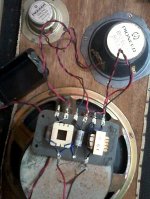
These are sealed enclosure 3 way speakers of about 14"W x 21"H x 12" D length. Panel size is 0.75 inch. Drivers are mounted from inside without any gasket on tweeter and midrange. i.e. they are recessed if seen from front like a horn.
The Tweeter (8 ohms10W. Cone diameter 2") and Midrange (8 ohms 30W, Cone diameter 4.5") are sealed back drivers. The woofer is (8 ohms 60W. approx. cone diameter 8") with typical open basket. There is no stuffing inside enclosure. The enclosures do not seem to be sealed as there is a gap in corner on back panel due to particle board disintegrating. The Sound is goodishly OK. 🙂
Crossover is like this : A 2.8uf Capacitor in series to Tweeter's +ve terminal. An inductor (unknown) and 10uf capacitor in series with Midrange +ve terminal. The woofer has an indiuctor in series with stamp mark on it as 0.64 which I think is mH.
Kindly advice and give info about following.
1) Can crossover points be identified by these component values ? I checked with online 3 way 1st order crossover calculator and crossover point came to be about 875hz and 7000hz ?
2) Will stuffing inside with foam help ?
3) Midrange is little bit shouty Can I attenuate it with Lpad two resistors ? what values and where ?
4) Will flush mounting (from front) mid range and tweeter with some gasket help ?
5) The panel being 0.75" and woofer driver being very heavy I am thinking of supporting the heavy magnet inside by a wooden baton attached to bottom of the enclosure. is that OK ?
6) I presume this is 1st order crossover and tweeter/mid range being sealed back; they must be having band limited response so combined with 1st order crossover will this be considered pseudo 2nd order crossover ? (The over all sound do seem very coherent)
7) Any pros and cons about these sealed back drivers ?
8) If I stuff inside with foam will the decreased volume affect woofer response ? It already sounds punchy and good. A little extension at lower end will help though. But I think it may be because the enclosure has air leaks. Right ?
Veneer of enclosure is peeling away and enclosure is not air tight. I also think it will benefit from little bracing inside. But I need to see how much it costs to refurbish the enclosure. Right now things are little hectic personally. But they sound good, so In coming weeks to learn I may try to mod this after your advice. Thanks very much in advance.
Regards
Hiten
I perfectly understand without driver parameters we cant make or mod good speakers but kindly help me understand and learn about DIY 3 way speaker (See picture attached) as I have very basic understanding of this things.
These are sealed enclosure 3 way speakers of about 14"W x 21"H x 12" D length. Panel size is 0.75 inch. Drivers are mounted from inside without any gasket on tweeter and midrange. i.e. they are recessed if seen from front like a horn.
The Tweeter (8 ohms10W. Cone diameter 2") and Midrange (8 ohms 30W, Cone diameter 4.5") are sealed back drivers. The woofer is (8 ohms 60W. approx. cone diameter 8") with typical open basket. There is no stuffing inside enclosure. The enclosures do not seem to be sealed as there is a gap in corner on back panel due to particle board disintegrating. The Sound is goodishly OK. 🙂
Crossover is like this : A 2.8uf Capacitor in series to Tweeter's +ve terminal. An inductor (unknown) and 10uf capacitor in series with Midrange +ve terminal. The woofer has an indiuctor in series with stamp mark on it as 0.64 which I think is mH.
Kindly advice and give info about following.
1) Can crossover points be identified by these component values ? I checked with online 3 way 1st order crossover calculator and crossover point came to be about 875hz and 7000hz ?
2) Will stuffing inside with foam help ?
3) Midrange is little bit shouty Can I attenuate it with Lpad two resistors ? what values and where ?
4) Will flush mounting (from front) mid range and tweeter with some gasket help ?
5) The panel being 0.75" and woofer driver being very heavy I am thinking of supporting the heavy magnet inside by a wooden baton attached to bottom of the enclosure. is that OK ?
6) I presume this is 1st order crossover and tweeter/mid range being sealed back; they must be having band limited response so combined with 1st order crossover will this be considered pseudo 2nd order crossover ? (The over all sound do seem very coherent)
7) Any pros and cons about these sealed back drivers ?
8) If I stuff inside with foam will the decreased volume affect woofer response ? It already sounds punchy and good. A little extension at lower end will help though. But I think it may be because the enclosure has air leaks. Right ?
Veneer of enclosure is peeling away and enclosure is not air tight. I also think it will benefit from little bracing inside. But I need to see how much it costs to refurbish the enclosure. Right now things are little hectic personally. But they sound good, so In coming weeks to learn I may try to mod this after your advice. Thanks very much in advance.
Regards
Hiten
Attachments
Last edited:
Hi Hiten!
I wouldn't do a thing until you measured. 🙂 If your speaker was popular enough you might even find already discussions about improving it.
Look into Room EQ Wizard and a calibrated microphone. You can also do impedance measurements, which you will need for each of the three drivers.
Without measurements it's impossible to know what your L-PAD values should be, but try some resistors in series with your mid as a learning exercise! 🙂 Get maybe 1, 2 and 4 Ohm resistors so you can try a range of values. Of course, get cheap 10W resistors for this experiment. Also, without knowing the driver impedance, it is impossible to tell what the filter effects where, as they are interdependent.
I leave you with this link to my blog about crossover basics:
https://speakermakersjourney.blogspot.com/2016/02/crossover-basics.html
Best,
E
Last edited:
1. No.
2. Stuff it with mineral wool or pillow stuffing.
3. Put 3.3 or 4.7 ohm resistor serially with the midrange.
4. Usually it requires some woodworking, but if not, go for it. Do not expect spectacular gains.
5. No, much better is to stiffen the front board with wooden bar glued just above woofer.
6. No, sealed back drivers behaves like 2nd order high-pass filter, so with electrical 1st order crossover total combination is 3rd order below driver resonant frequency. But real acoustical crossover frequencies are well above that resonant frequencies.
7. Irrelevant.
8. Do not stuff it with foam. Mineral wool or pillow stuffing are 99% air. Stuffing will help. Seal the leaks and brace inside.
Crossover points can't be identified unless you have impedance plots, easy to do with ATRA's LIMP module & a simple jig. This will also give a reliable basis for redesigning the crossover if you wish to later.
I'd say it's time for a new box, 12mm ply suitably braced & lined with felt is my preference.
Stuffing with foam increases the apparent volume, but slightly rolls off the bass end, i.e. the system will respond a bit lower, but with slightly lower level
This may help with L-pad calcs: L pad calculator - attenuation dB damping impedance decibel loudspeaker speaker voltage divider - sengpielaudio Sengpiel Berlin
Thanks gentlemen. I will start by stuffing the enclosure, repairing air leaks and bracing the panels.
eriksquires, your blog is amazing resource. I will start with basics. Thanks very much.
Regards,
eriksquires, your blog is amazing resource. I will start with basics. Thanks very much.
Regards,
Hello,
I did a basic (little unprofessionally by me) measurements of all drivers. The common method of measuring voltage across series resistor at various frequencies at constant voltage. Not very well implemented due to lack of frequency generator etc. but I did get the results which shows some similarity of same size drivers. So though not accurate I guess they are OK. The Resonant frequency came to about 35hz for woofer. 500hz for midrange. and tweeter was very difficult to measure but I think it is around 6500 hz. (Tweeter is approx. 2" paper cone) I also checked the old capacitors. Values are little higher then printed/specified. What would be the new crossover component values of 1st order crossover if I want to avoid these resonant frequencies ? I would like to try this and see the difference. Can any help in this regard ?
Thanks.
No need for a new crossover, just replace electrolytic capacitors with new ones (with the same values!).
- Status
- Not open for further replies.
- Home
- Loudspeakers
- Multi-Way
- Kindly investigate/advice about this 3 way speaker