Hi,
I've tryed to sim nearly every to mix 2x4" and a 12" laying around, with hornresp until it offers multi-entry horn. So, the final project wich motivate me a lot :
_Full system around 110-130 liter.
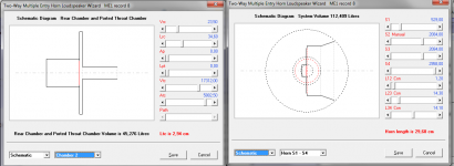
_One 12" woofer in closed back and front bandpass horn loaded, with a long 33cm throat port going to the horn mouth, very near the two 4" mouth.
_The 4" loaded in very small box.
_Shared "horn".
_analog LR2 filters + all pass delay (+2 natural roll off )
_2 way active
With hornresp, i manage to tweak both to get a beautiful joining response with a 350hz LR2 high pass and a 390LR2 low pass, adding to natural roll offs of both kind of loading, but i'd like to adjust phase with delay to take account of the long bandpass path.
Sims lead me to big horn mouth allowing both virtual mouth really near.
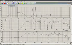
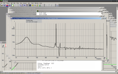
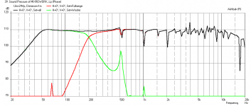
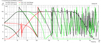
Without understanding how to deal with different gain, delay and crossover with akabak now, i came to the sim shown. Up, only woofer connected. Middle, only the high way, and bellow, of course the brut summing. Akabak file joined. Don't understand why need half power with akabak for high...don't know if it deals well with the two speaker exported directly from hornresp.
I volontary roll off speaker response tweaking horn at 10khz, not to excite too much cone resonances, and with the idea of adding a fostex ft17h later.
Closed back bandpass front horn loading allow lower group delay for lows, maybe lower distortion, and . And 130L stay small for a bass cab.
24Vpp 108db => 4,8mm excursion on the 12" of 7mm xmax. 108db given for 12Vpp with Akabak => 1mm for the 4" of the 2,2mm xmax ( 108db with 24Vpp with LR2 in hornresp=> 0,7mm).
108db is only for headroom.
I've measured only the 12", for the 4", i use datasheet. The 4" are kind of full range with phase plug, not measured yet.
I use akabak on a old linux computer with wine, and hornresp on a recent windows.
Thanks for helping !
I've tryed to sim nearly every to mix 2x4" and a 12" laying around, with hornresp until it offers multi-entry horn. So, the final project wich motivate me a lot :
_Full system around 110-130 liter.
_One 12" woofer in closed back and front bandpass horn loaded, with a long 33cm throat port going to the horn mouth, very near the two 4" mouth.
_The 4" loaded in very small box.
_Shared "horn".
_analog LR2 filters + all pass delay (+2 natural roll off )
_2 way active
With hornresp, i manage to tweak both to get a beautiful joining response with a 350hz LR2 high pass and a 390LR2 low pass, adding to natural roll offs of both kind of loading, but i'd like to adjust phase with delay to take account of the long bandpass path.
Sims lead me to big horn mouth allowing both virtual mouth really near.
Without understanding how to deal with different gain, delay and crossover with akabak now, i came to the sim shown. Up, only woofer connected. Middle, only the high way, and bellow, of course the brut summing. Akabak file joined. Don't understand why need half power with akabak for high...don't know if it deals well with the two speaker exported directly from hornresp.
I volontary roll off speaker response tweaking horn at 10khz, not to excite too much cone resonances, and with the idea of adding a fostex ft17h later.
Closed back bandpass front horn loading allow lower group delay for lows, maybe lower distortion, and . And 130L stay small for a bass cab.
24Vpp 108db => 4,8mm excursion on the 12" of 7mm xmax. 108db given for 12Vpp with Akabak => 1mm for the 4" of the 2,2mm xmax ( 108db with 24Vpp with LR2 in hornresp=> 0,7mm).
108db is only for headroom.
I've measured only the 12", for the 4", i use datasheet. The 4" are kind of full range with phase plug, not measured yet.
I use akabak on a old linux computer with wine, and hornresp on a recent windows.
Thanks for helping !
Attachments
Last edited:
In Akabak, model each driver and its box and horn if applicable in its own 'System' on same script. In each system, apply the filter of your choice - LR2, BW4, etc high pass or low pass or both - use the manual to see examples. Time alignment can be done with simple delay statement in each system - good for DSP delays. All pass filters are also available but delays on that is tricker to work with. The first term of each filter is the gain. Set to 1 or 0.5 or 2 etc. it's linear gain so 0.5 is -3dB relative to overall global system.
The when plotting result - choose each system as one line red or green and plot total as black. Only 3 lines allowed so max is 2 way with overall or 3 way but no overall.
You can save traces as txt file and plot with another program like REW.
Here is an example of the output I can get for modeling a 2 way point source multiple entry horn as shown in the bookshelf horn thread:
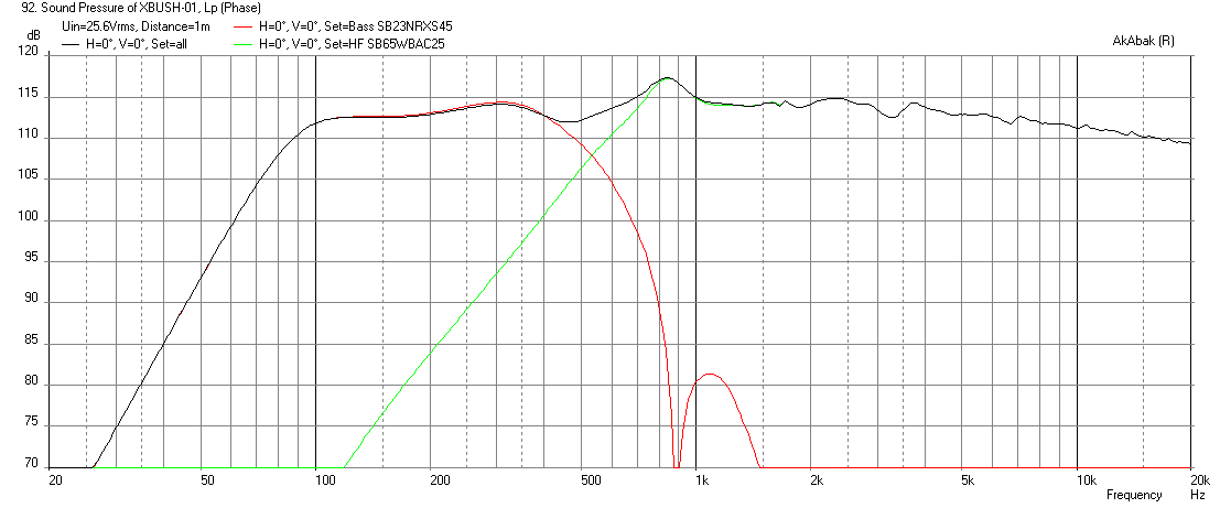
2 systems are used and it's the same waveguide in each system but with different drivers active and each with its own filter for the band pass on the woofer and a high pass on the mid/tweeter.
The when plotting result - choose each system as one line red or green and plot total as black. Only 3 lines allowed so max is 2 way with overall or 3 way but no overall.
You can save traces as txt file and plot with another program like REW.
Here is an example of the output I can get for modeling a 2 way point source multiple entry horn as shown in the bookshelf horn thread:
2 systems are used and it's the same waveguide in each system but with different drivers active and each with its own filter for the band pass on the woofer and a high pass on the mid/tweeter.
Last edited:
THANKS !
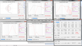
I just had time to reworked the full script as suggested just after getting my first 3y old son to bed, and until now ready for the 9 month son's milk ^^
Compared to hornresp crossover sim, i just reduced high way gain to 0,8, added a delay coresponding to bandpass front chamber + throat lenght, without any stuffing added. Lot of place for tweaking more 🙄
Used same scale as your example to make comparison easier, simed at 24vpp.
Max 112db@woofer xmax 45-20khz +/- 3db @24vrms
Attachments
Last edited:
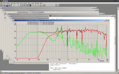
That looks better but you have a lot of HF leakage from your woofer. Are you running a low pass filter or just relying on the acoustical bandpass action? Try adding a 12dB/octave Butterworth low pass at circa 250Hz.
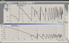
Well view ! Ooops, low pass was disactived !
Tweaked a bit and came to LP LR2@450hz HP LR2@280Hz.
Need to deal with natural low pass, so can't go lower than 450hz, nor 280hz. There's a small bandwith windows were it can work flat.
Will have to well "flare" bandpass port to reduce those 2 spikes, and add front and rear volume stuffing.
EDIT : added group delay plot ^^
Edit bis : added phase (even if i don't really know how to interpret...)
Attachments

Last edited:
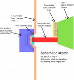
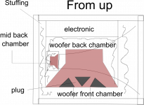
Can you show a diagram or sketch of the design? I don't understand why the woofer LP filter is 450Hz when it looks like the natural bandpass is 200Hz? And you say you have a bandpass port spike at 450Hz? I guess you have a rather long bandpass port? What you might want to do is adjust front chamber volume on woofer to be smaller and port length shorter but area smaller. Kind of like how a flat board with a hole is placed in front of a woofer. You can even put a volume filler plug behind baffle and between cone to bring volume lower and push bandwidth extension higher up. That will let you have a smoother Xo workout resonance peaks.
Thanks a lot X ! Partial diagram is shown in first post in hornresp capture screen. About bandpass, it's around 23liter back chamber,
, front chamber is yet only 3cm long for around 17liter, so needs "plug" yet...Port is around 120cm2/30cm, and still is small for tuning/power. Cannot do a lot better without trying to sim a really flared port.
In hornresp sim, it take account of back chamber stuffing wich yet helps dealing with it.
I have to deal with the high woofer inductance, and so the natural bandpass is far from perfect. If i lower the electric low pass, i lost too much bandwith, and cannot compensate with the fullrange (fs=125hz qts=0,4). It's really fast and intuitive tweaking around crossover freq with hornresp, even without at first don't understanding fully what happen ^^ As shown in first akabak sim in first post without any filter, the "response summing windows" is really small.
But as said, i will have to loop between akabak/hornresp for futhermore tweak this all.
Just tested something : custom low pass factor 1, flatten even more response.
Last edited:
Having a hard time understanding the diagram. I see what looks like a tiny chamber followed by a rapidly expanding horn and a huge offset driver connected to the throat where tiny chamber expands to horn?
A tip for plotting Akabak diagrams. In file menu there is a copy to bitmap option that saves a PNG file of active window. Then you don't need to do screen captures which gets the whole desktop - which you probably don't need to show.
A tip for plotting Akabak diagrams. In file menu there is a copy to bitmap option that saves a PNG file of active window. Then you don't need to do screen captures which gets the whole desktop - which you probably don't need to show.
That's a most interesting speaker topology - why such a long bandpass port?
The sudden expansion of the woofer bandpass port at the "horn" can be made more efficient with a gradual expansion - or is that equivalent to wall injection on the horn which is mainly to support the two sealed mids? Where is the HF coming from, the mids or full range drivers?
Low way is closed back and not reflex, so port is long only way to lower the tuning, without needing a higher "compression ratio" than 1:4. Since it reach 45hz, port resonnance (as seen) and chuffing became a concern. Don't know if other kind of speaker would have needed a so long port. Maybe not the most suitable speaker for it ? It's in fact more a subwoofer with fs=30 and xmax=+/-7mm, and Le=3,46mH...
Small back chamber of low way keep excursion low, without need of any high pass.
High freq came from the 2x4". There's only 2 ways. I think those 4" could have interested you for their impressive bandwith, good price, the use of phase plug...etc Those are neither fullrange (fs=125hz), neither midrange (not enough efficiency), but extended mid-high. Look at voicecoil lengh, and airgap and compare to some faital...not so bad, but here qts=0,4 ^^
I bought those speaker first 3 years ago, pretty sure i would fine a way to marry them, and only found a topology that interest me those days....
Last edited:
Ok, I was wrong in my script, put 30 cm front chamber, you were totally right, sorry, corrected to 3cm. Added 3 liters to front chamber, compensated by changing a bit horn profil for not expansion during the first 14,4 cm, for the loose of bandwith. Ajusted low Q of woofer with 3 liters more in back chamber. Total volume is now 117L with hornresp. Oh, adjusted filters too for custom high pass 270hz 2th with damping of A2=1,2. And for low pass, damping A2=1 and freq =330hz. Better ! Thanks X !
Attachments
Last edited:
110db at 24Vpp , excursion of 4,5mm /7mm pp for woofer, and 0,9mm /2,2mm for fullrange. 110db was a objectif for headroom/dynamic since it's for instrument.
Full xmax is reached at 24Vrms, 112db for woofer; and 38Vrms, 117db for fullranges.
In fact playing with hornresp, the topology seems to work with horn boosting mids low where each system gave up of gaz, and so it extend both bandwith... Final extension helps shaping the response. I'm maybe wrong, i suppose only, and the idea seems me cool so i'm maybe too subjective ^^ I past a lot of time reading everything you do all, but i'm at million light years of you experience X.
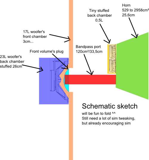
For the sketch, here a hornresp's more useful to see proportion now that i put the colored principe sketch.
It's night here, 1:38 at clock, all the family at bed. Will put some wood in the fireplace. Very happy of tonight's result. Next step, is to measure real 4" parameters.
(It would work with only 1x4", with nearly reaching at 110db, but i'm more concerned about the cone, of only 3,9g mms, and would need to much power)
Full xmax is reached at 24Vrms, 112db for woofer; and 38Vrms, 117db for fullranges.
In fact playing with hornresp, the topology seems to work with horn boosting mids low where each system gave up of gaz, and so it extend both bandwith... Final extension helps shaping the response. I'm maybe wrong, i suppose only, and the idea seems me cool so i'm maybe too subjective ^^ I past a lot of time reading everything you do all, but i'm at million light years of you experience X.
For the sketch, here a hornresp's more useful to see proportion now that i put the colored principe sketch.
It's night here, 1:38 at clock, all the family at bed. Will put some wood in the fireplace. Very happy of tonight's result. Next step, is to measure real 4" parameters.
(It would work with only 1x4", with nearly reaching at 110db, but i'm more concerned about the cone, of only 3,9g mms, and would need to much power)
Attachments
Last edited:
Project change, sorry got inspired again ! Foam core board is so easy (thx X !)...and discovered tulip horn in export tool of hornresp(thx David!)...
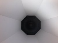
Now it's a 3way synergy/unity tulip horn with long throat bandpass closed back woofer with a bullet horn in front ^^
Only need 1x4" now, but cheated with 2 hyperbolic segment horn to get efficiency higher (now more directional), + added a pince of resistance to artificially get lower inductance. Measured parameter of the 4" are as for the 12", really near the datasheet but lower BL and so higher Qes/qts ...finally, qts is more around 0,6 than 0,4 as in spec.
Reduced efficiency of the woofer with smaller bandpass throat. Discovered high frequency inverting phase stuff in akabak for at around 5khz. Tweaking at phase/impulse, now it only need 2 low pass, one 2th for the woofer wich deserve too as time alignement, and a 4th at 4khz to cross with a jbl st200 bullet horn tweeter, so no high pass for the 4". I'll need allpass for the tweeter, since it will be at the center and in front of the tulipe horn. Such a big horn coupled with bullet horn will surely deal with directivity problem, but it's such a fun ^^
First : Hyperbolic tulip horn waveguide in 1,5mm foamcore board => done !
Attachments
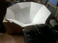
Just done with inkscape, using hornresp export files as guide, printed at 1:1, scissored printed profil, and used as template for 2 hour foamcore cutter cutting. The hardest part is bending last segment, foamcore board folded instead of bending (hard word choice...does it make sense in english?). But i realise that i did it wrong using lenght variable as guide instead of side lenght so it's 6cm too short...dooo ! ^^ Let's do it again !
Last edited:
If you read foam core thread, there are tips on bending smoothly. Use razor to lightly cut or score lines on the concave side of the bend every 3 to 10mm depending on how sharp of a bend. Cut enough to pierce through outer paper layer but not all the way through. Then use a round form like a pipe or tube to pre bend the panel before glueing. I lay scored foam board on carpeted floor and use round pipe to roll it to get the pre bent curves. This prevents the folding or buckling. You can paint the scored surface with PVA glue to seal the small cuts after main joints are glued.
If you really want a high efficiency horn - try the tractrix in the Trynergy thread. +10dB gain. All the patterns for cutting in first post links.
http://www.diyaudio.com/forums/full...ing-trynergy-full-range-tractrix-synergy.html
If you really want a high efficiency horn - try the tractrix in the Trynergy thread. +10dB gain. All the patterns for cutting in first post links.
http://www.diyaudio.com/forums/full...ing-trynergy-full-range-tractrix-synergy.html
Thanks for the tips, i thought about it, but i've been a bit optimistic. I think i'll add 3cm foam behing to damp and harden, and use fiberglass for inside surface hardening.
I tryed simulating traxtrix, but i did not manage to get enough level in low range...I ended using 1 con segment + 2 hyperbolic segment with T=0,7.
Cabinet folding will be another fun part in such configuration ^^
I tryed simulating traxtrix, but i did not manage to get enough level in low range...I ended using 1 con segment + 2 hyperbolic segment with T=0,7.
Cabinet folding will be another fun part in such configuration ^^
Attachments

Interesting configuration. You want to keep that bandpass port as short as possible to extend upper HF extension, reduce band pass peak overshoot amplitude, and improve efficiency. Enter from top of tulip horn wall where shorter or to the side even.
- Status
- Not open for further replies.
- Home
- Loudspeakers
- Multi-Way
- (Kind of) unity horn/akabak gain-delay-phase help needed