amp wras gave to me, powers on, has sound, but terrible distorted. fuse holders and one of the speaker terminals melted. any help is appreciated
You may want to move to car audio sub forum.
Do you have a scope?
Check with DC volt meter, black probe on power GND terminal, the rail voltages, pins on input board, speaker terminals.
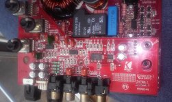
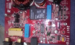
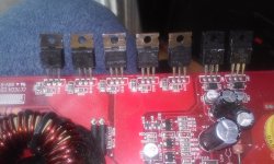
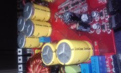
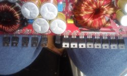
Post good quality pics of board. One overall, detail of output section, input board and underneath input board.
Do you have a scope?
Check with DC volt meter, black probe on power GND terminal, the rail voltages, pins on input board, speaker terminals.
Post good quality pics of board. One overall, detail of output section, input board and underneath input board.
What does the R# silkscreened near resistor say. I can check my schematics to determine value.Also has a burnt resister I can't I.d.
sorry, no scope. the distorton is very bad. R36 is # for bad resister, i removed it. c35 looks wrong to me to. The caps seen ok, but look like vinyl jacket has slid down.
Attachments
-
 14515773677371253156044.jpg807.1 KB · Views: 128
 -
 1451577470799-1614564403.jpg314 KB · Views: 117
 -
 1451577515463-667543643.jpg358.2 KB · Views: 131
 -
 14515775366411692234100.jpg380.3 KB · Views: 118
 -
 1451577558213-1688904962.jpg904.5 KB · Views: 124
 -
 1451577665215-1506187409.jpg923.5 KB · Views: 94
 -
 14515776388391472349439.jpg937.9 KB · Views: 78
R36 is a 100 ohm 2w resistor and is the RC with C35-1UF cap for damping the power transformer.
C35 appears to have been touched by a soldering iron.Check its value out of circuit if possible, if it is shorted or leaking that may be the reason R36 is out of value.
Once you replace R36 and C35,you should be able to power board outside chassis. I recommend you use 10 amp fuse for this purpose, and monitor outputs and power supply mosfets for excessive heat. With no load and input signal and black probe on power GND terminal,check rails, and 5 pins on input board and post.
You can check the to see if the outputs are firing, with a voltmeter across the outside leads of outputs IRF640's and IRF9640's. Checking one output per bank or span across each bank will be sufficient,Careful, do not slip or you will be replacing outputs and mosfets!!!.Post your results.
is the 4band resistor with 100ohm, and 2w = 2.0? also the 1uf cap, should it ohm the same each way? also its marked 222 & 63v. would a 224 & 100v work? I will post meter measurments soon, thanks so much
Not sure what you mean by 2.0? R36 is a 100 ohm 2 watt resistor.
My mistake, C35 a .0022 uF 630v. It should read high or open both ways. You may see some charging depending on the ohmmeter, my Fluke 77 shows open both ways.
As far as the filter caps, the vinyl jackets tend to slid down due to ambient heat, and shouldn't be a problem.
My mistake, C35 a .0022 uF 630v. It should read high or open both ways. You may see some charging depending on the ohmmeter, my Fluke 77 shows open both ways.
As far as the filter caps, the vinyl jackets tend to slid down due to ambient heat, and shouldn't be a problem.
- Status
- Not open for further replies.
- Home
- Amplifiers
- Class D
- kicker zx750.1