Hello diyaudio family
In my examination, there is no problem with the supply MOSFETs and output MOSFETs. The output driver transistors are solid.
The problem with my device is that when I disconnect the lm361n, the power led turns from green to red and repeats this over and over.
But when the lm361n is plugged in, the power LED is fixed in green and the relay does not turn on and the device draws excessive current and the supply mosfets start to heat up.
When 7912 and 7812 are removed, the relay opens.
I suspect LM361n, can you help me where else should I look?


Unfortunately I don't have an oscilloscopeDo you have a scope?
With the LM361 out of the circuit and pad 11 of the 361 connected to the negative terminal of C274, does the power LED stay on?
What are the DC voltages on the 4 power supply terminals of the LM361?
What is the DC voltage across the four 12v Zeners (D121 and 3 other similar)?
What are the DC voltages on the 4 power supply terminals of the LM361?
What is the DC voltage across the four 12v Zeners (D121 and 3 other similar)?
When the pad 11 of the 361 is connected to the negative terminal of the c274, yes the power LED turns on and the relay is activated
All four zener diodes provide 12v


All four zener diodes provide 12v
Solder a bridge between pins 1 and 2 of U11.
DCV on pins 3 and 4 of the LM361?
Does your multimeter have a frequency counter on it?
DCV on pins 3 and 4 of the LM361?
Does your multimeter have a frequency counter on it?
I bridged pins 1 and 2 of U11 With pad 11 of the 361 and C274 negative terminal also bridged No DCV between pins 3 and 4 of 361 I have a frequency counter in my multimeter
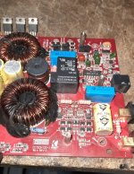
It may be worth noting the output inductors L105,L106 look to be discolored from excessive heat and possibly may have shorted windings. The sleeves on the inductor leads may have become perforated and at the very least should be replaced. We (Kicker Repair Department) use a braided rubberized fabric tubing. I don't know the vendor or product code, but will check Monday and reply.
No matter what I did, it didn't work, I changed the lm361n, the problem still didn't go away, I connected a lamp and when the device is turned on, as can be seen from the lamp, it draws current and does not turn on the relay.
I only helped with this because PapaZBill hadn't been here. Since he's back, I'll let him finish this.
Like he stated, at least one inductor appears to be in need of help and will need to be taken out of the circuit. Desoldering one lead may be enough to get the circuit to function well enough to test the drive out to the FETs.
Does your meter show duty cycle for frequency?
Did you remove the bridge from the op-amp?
I removed the bridge from the opamp, reassembled the LM361 into the circuit, a new development occurred, I noticed that the output stage was getting hot, and when I disconnected the A1381 C3503 from the circuit, the device turned itself on with the relay.
Attachments
[COLOR=var(--YLNNHc)]Yes, very interestingly, the device produces sound without the a1381 and c3503, and the bass works actively 😃[/COLOR]
The amp has two parallel sections. One is working. I believe the old 361 was defective and would have needed replacement (as you have done).
Desolder one terminal of the inductor with the blackened windings and see if the drivers still heat up after installing them.
Do you see a darkened ring in the bottom of the circuit board under the inductor with blackened windings?
Desolder one terminal of the inductor with the blackened windings and see if the drivers still heat up after installing them.
Do you see a darkened ring in the bottom of the circuit board under the inductor with blackened windings?
- Home
- General Interest
- Car Audio
- Kicker ZX750.1 overcurrent problem