The screenshots of U14-Pin 4 tell me the that U14-LM361 or U11-TL072 have failed.
Using a jumper wire ground U14-Pin 3 to signal ground. Look for C275- 10Uf/16v positive lead and solder other side of jumper there. If you are not sure use an ohmmeter to check for continuity from C275 and the negative speaker terminal. The side that has continuity(~0 ohms) is where you want the jumper wire soldered.
Once the jumper is in place probe U14 Pin 11 and post screenshot.
When you ground U14 Pin 3 it disables the feedback loop.
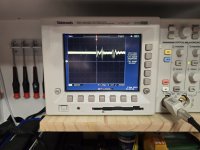
If U14 Pin 13 has a 5v p-p square wave the IC is functioning. But your screenshot says otherwise.
Is your scope probe tied to signal ground?
If so I would replace U14-LM361.
If U14 Pin 13 has a 5v p-p square wave the IC is functioning. But your screenshot says otherwise.
Is your scope probe tied to signal ground?
If so I would replace U14-LM361.
It was connected to signal ground.
I ordered these awhile back thinking these were the culprits but not sure if they are the right ones now? Expected delivery this week. Can you tell me if this one will work? Thanks for your help!

I ordered these awhile back thinking these were the culprits but not sure if they are the right ones now? Expected delivery this week. Can you tell me if this one will work? Thanks for your help!

Replaced LM361 and she's breathing again. Thanks for your help, you guys are truly amazing. Now can you fix the stock market, I'm retired and it's killin me lol...
- Home
- General Interest
- Car Audio
- Kicker ZX750.1 No Audio