Is it possible that the 12v supply is simply shutting down when all of the FETs are in the circuit?
Or are you saying that you have drive when there is no voltage on the drains?
Or are you saying that you have drive when there is no voltage on the drains?
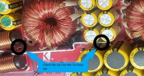
The B+ voltage flows...
B+ terminal
Inductors
Primary windings of the power transformer
Drains of PS FETs.
Find the break.
B+ terminal
Inductors
Primary windings of the power transformer
Drains of PS FETs.
Find the break.
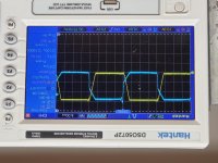
What side of the transformer are you looking at and are the blue and yellow traces from different transformers?P-P values? Frequency? More info is better.
If you don't have excessive idle current and your rails,+/-12 volts look good,this may be normal.
How did you get the power supply working?
If you don't have excessive idle current and your rails,+/-12 volts look good,this may be normal.
How did you get the power supply working?

The amp turns on and idles at 1.3. When its working correctly it was idling at 1.7. There is no switching on the output fets.
All measurements taken with my power supply at 12.4v
The positive and negative rails both sit at 106v
Dc across the caps is 11.15v on c6 and 14.65 on c12
+DRV 4.93 -DRV 4.93
All measurements taken with my power supply at 12.4v
The positive and negative rails both sit at 106v
Dc across the caps is 11.15v on c6 and 14.65 on c12
+DRV 4.93 -DRV 4.93
What about the other test points on J200?
The +/- 12 volt points should be 15 volts.
OCP and SFB(J101?) also?
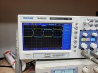
Check +DRV and -DRV with a scope.
Check C11-should be the same as C12. My intention was to box in both C11 & C12 and I shifted it too far to the right.
The +/- 12 volt points should be 15 volts.
OCP and SFB(J101?) also?
Check +DRV and -DRV with a scope.
Check C11-should be the same as C12. My intention was to box in both C11 & C12 and I shifted it too far to the right.
-drv only has .3mv now.
There are no waves to see on either + or - Drv
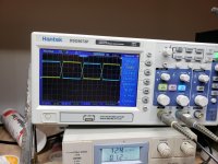
C11 and C12 both have 14.75vdc
Both +/- 12 are at 15v
Ocp is 5v
Sfb is 1.5v
There are no waves to see on either + or - Drv
C11 and C12 both have 14.75vdc
Both +/- 12 are at 15v
Ocp is 5v
Sfb is 1.5v
Because you have .3mv on -DRV and no waveforms on either -DRV and +DRV and there should be nothing on the SFB line something in the drive circuit has failed, or but less likely the feedback loop is open.
Check the following components:
Q100(+DRV) & Q102(-DRV)-2SD669
OPT100 & OPT101-HCPL0601N
U100 & U101-IR4426S
D100 & D106-1N5241B 11V zener
D101 & D107-1N5231B 5V zener
Use C11(negative side) for the +DRV reference(Black Probe)
Use C12(negative side) for the -DRV reference(Black Probe)
Check first with an ohmmeter and a DC Voltmeter at each pin of the active components
and post results
Last edited:
- Home
- General Interest
- Car Audio
- Kicker zx1500.1