I got 2 of theese amps in for repair i believe they have the same problem.
Amp has no output.
I checked for rail voltage at outputs i have nothing .
I checked power supply fets with amp powered up black prob on chasis ground
Leg1:0
Leg2:13.92
Leg3:0
The reading are from the power supply fets IRF44's
wondering what to check at this point?
Amp has no output.
I checked for rail voltage at outputs i have nothing .
I checked power supply fets with amp powered up black prob on chasis ground
Leg1:0
Leg2:13.92
Leg3:0
The reading are from the power supply fets IRF44's
wondering what to check at this point?
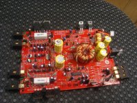
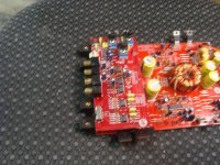
A photo of the inside of the amp would be helpful.
The voltage on the 494?
IC#
Pin 1:
Pin 2:
Pin 3:
Pin 4:
Pin 5:
Pin 6:
Pin 7:
Pin 8:
Pin 9:
Pin 10:
Pin 11:
Pin 12:
Pin 13:
Pin 14:
Pin 15:
Pin 16:
The voltage on the 494?
IC#
Pin 1:
Pin 2:
Pin 3:
Pin 4:
Pin 5:
Pin 6:
Pin 7:
Pin 8:
Pin 9:
Pin 10:
Pin 11:
Pin 12:
Pin 13:
Pin 14:
Pin 15:
Pin 16:
Ok i repaired a few solder joints on the rectifiers and now on the outputs i have 27.89 On the middle leg of tip 35
On tip 36 i only have 2.24 on the middle leg
tl494
1:1.08
2:3.64
3:.06
4:0
5:1.51
6:3.42
7:0
8:12.32
9:5.16
10:5.16
11:12.32
12:13.89
13:5.03
14:5.03
15:5.03
16:4.32
On tip 36 i only have 2.24 on the middle leg
tl494
1:1.08
2:3.64
3:.06
4:0
5:1.51
6:3.42
7:0
8:12.32
9:5.16
10:5.16
11:12.32
12:13.89
13:5.03
14:5.03
15:5.03
16:4.32
Attachments

Assuming that you used the secondary center tap as the reference, the lack of voltage could be caused by...
open rectifier
broken connection on rectifier
broken connection on jumper wire connecting the rectifier to the outputs
open rectifier
broken connection on rectifier
broken connection on jumper wire connecting the rectifier to the outputs
Ok i repair the issue with the rectifiers i now have both postive and negative rail voltages on outputs.
Still no output from either amp.
wondering where i go from here?
Still no output from either amp.
wondering where i go from here?
Is the preamp board connector labeled to show the left and right signal pins?
If so, see if there is audio at that point.
Have you run all pots and switches through their entire range?
If so, see if there is audio at that point.
Have you run all pots and switches through their entire range?
On the connecter pins its labled R -15 SGND +15 L
Pin1:.01
pin2:-14.57
pin3:.04
pin4:14.65
pin5:.09
If that helps any
Pin1:.01
pin2:-14.57
pin3:.04
pin4:14.65
pin5:.09
If that helps any
You'd have to drive the input with a strong signal and measure the AC voltage on the L and R pins.
i drove the inputs with 8 volts and measured the left and right pins
left pin:14.79 volts
right pin:14.33 volts
meter set on ac
left pin:14.79 volts
right pin:14.33 volts
meter set on ac
Follow the traces from the L and R pins (on the main board). What is the first transistor it goes to? It likely goes through a resistor before going to the transistor.
Is one leg of that transistor connected to the secondary center-tap?
Is one leg of that transistor connected to the secondary center-tap?
Looks like they go to a set of mpsa42's and then looks like 1 leg is connected to the secondary center tap
Ok the voltages on mpsa42's
1:-26.36
2:-26.36
3:13.85
I also found some 2n4401's in that same area witch i believe connect to the op-amps on the preamp board
and the voltages are
1:0.67
2:0.67
3:13.86
so then i tested all opamps and all measure
1:0.67
2:0.67
3:0.67
4:13.86
5:0.67
6:0.67
7:0.67
8:15.26
1:-26.36
2:-26.36
3:13.85
I also found some 2n4401's in that same area witch i believe connect to the op-amps on the preamp board
and the voltages are
1:0.67
2:0.67
3:13.86
so then i tested all opamps and all measure
1:0.67
2:0.67
3:0.67
4:13.86
5:0.67
6:0.67
7:0.67
8:15.26
It appears that you're using the chassis ground for the reference. If you are, use the secondary ground for future measurements in the audio section.
Do you see a transistor marked Q100/Q200?
Do you see any that are marked J108, J110, J111...?
Do you see a transistor marked Q100/Q200?
Do you see any that are marked J108, J110, J111...?
The amplifier is muted. Pull them to see if the amplifier produces clean audio.
If so, follow the traces from leg 3 back to the power supply area. What transistor do they connect to?
If so, follow the traces from leg 3 back to the power supply area. What transistor do they connect to?
pulled the transistors amp produces clean audio from both channels.
As far as i can tell it looks like it goes back to a B649AL
and that reads
1:-11.25
2:-11.67
3:-11.66
As far as i can tell it looks like it goes back to a B649AL
and that reads
1:-11.25
2:-11.67
3:-11.66
I think there may be a bad solder connection at some point between that transistor and the muting transistors. Check the solder connections on the jumpers.
- Status
- Not open for further replies.
- Home
- General Interest
- Car Audio
- Kicker zx150.2