MatthewS, PapaZBill: Suddenly, I feel like a dummy 🙂
U202 - I did not go directly to the pin 6 to get my -12V reading. I was using that conveniently placed spot right in front to make my measurement. So yes where I'm correct in saying that spot in front of pin 6 is indeed positive rail, it in fact is not connected to pin 6. Pin 6 is getting is negative rail from somewhere else.
So now that I check directly to pin 6, we have -11.41V.
Guys, thank you very very much for guiding me past this crazy spot. I most definitely learned something on this one for sure. I knew something was screwy when the amp appears to be working, making correct patterns with the scope, but the voltages are wrong???? haha
Thanks again!
Sooo!
I bench tested this on low power with a speaker. Sounded good.
I got it ready for a higher power test. Put my bench supply on 19A just to see if it would survive a minute or two with a sweep from 100hz to 10hz. Nope! Hooked up my dummy load, powered it on, and my supply went into protect.
Now I’m getting what appears to be shorted IRF3205’s in the power supply section. None of the gate resistors are blown. Not a pop, snap, crackle or anything. This amp came in with blown outputs. Am I missing something here? I’ve never had an amp beat my *** this bad before lol
What do I replace/check before I tear this thing down?
I didn't see a post explaining what all was replaced in the first place. Just that it had bad outputs. Did you work on the PS? If so, did you scope the drive waveforms prior to reinstalling parts? Have you confirmed the outputs are all still good? What were you current limiting at prior?
Did not work on the power supply. The supply has IRF3205’s in it. I’m not even sure those are correct. Only outputs that were short when it came in was Q106 and Q108.
The power supply drive waves were good. The outputs are not currently shorted, just power supply fets.
I do notice however the batch stamp on one of the power supply fets to be different. Q30.
The power supply drive waves were good. The outputs are not currently shorted, just power supply fets.
I do notice however the batch stamp on one of the power supply fets to be different. Q30.
Start by removing all IRF3205's.
Once removed check with a scope the drive at the TL594 U2-Pins 9&10, and the sawtooth wave at Pin 5. post screenshots.
The mosfets may have been weak, or they where not properly clamped down. Check for perforated thermal pads.
You may need to replace Q24,27-2SD667 and Q25,26-2SB647, and use fresh batch matched IRF3205's
Does any one particular MOSFET read lower from G to S/D when reading ohms? If so, remove it and retest the bank. If you get all the bad ones out, repower limiting to < 5a and run the usual battery of signal tests.
EDIT: I was typing this reply when PapaZBill was posting his.
EDIT: I was typing this reply when PapaZBill was posting his.
Last edited:
Did not work on the power supply. The supply has IRF3205’s in it. I’m not even sure those are correct. Only outputs that were short when it came in was Q106 and Q108.
The power supply drive waves were good. The outputs are not currently shorted, just power supply fets.
I do notice however the batch stamp on one of the power supply fets to be different. Q30.
This may well be the culprit. I always replace with same batch. I've been bitten this way one time too many times!!
Removed all power supply fets. Seems as if only one blew. Oh well, throwing all - taking zero chances.
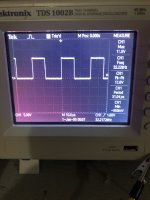
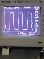
Image 1 - U2 - pins 9 and 10 scope output - they both are the same
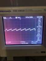
Image 2 - U2 - pin 5 - sawtooth output
Image 3 - Power supply fets at the gate pads - all of them look like this
PapaZBill: I agree. I'm going to end up replacing the power supply fets and the drive transistors. I can't imagine the one fet causing a problem to blow them, but again, not feeling taking any chances.
As a practice, this is what I would do. With this amp, is there anything else I should be replacing??? Seems as the more I get good drives the more I get stung! 😀
Image 1 - U2 - pins 9 and 10 scope output - they both are the same
Image 2 - U2 - pin 5 - sawtooth output
Image 3 - Power supply fets at the gate pads - all of them look like this
PapaZBill: I agree. I'm going to end up replacing the power supply fets and the drive transistors. I can't imagine the one fet causing a problem to blow them, but again, not feeling taking any chances.
As a practice, this is what I would do. With this amp, is there anything else I should be replacing??? Seems as the more I get good drives the more I get stung! 😀
Attachments

Quest components shows stock on both but i've never used them. Your drive signals looks perfectly fine. You can monitor them when the new FETs are installed for issues, but I suspect you'll be OK. You should measure the gate resistors even if they look fine.
Testing with no load on the driver circuit isn't definitive. The drive circuit needs to be loaded g-s on the FET pads with a small capacitor. I used a 0.047uF but anything close will suffice.
I usually recommend replacing drivers, just as a precaution. Follow Perry's advice from Post #31. If all looks good leave the original drivers.
I will look into what may be substituted in the meantime.
I will look into what may be substituted in the meantime.
I never dealt with Quest. One time if I recall when I tried, they wanted me to supply them with my company information - which I do not have...
I'd like to replace the driver transistors regardless. I've tried Perry's advice before with success. The transistors that you've listed as the replacements are not available however and the ones I mention look to be close. If you have a better substitution then I would rather use that.
I'd like to replace the driver transistors regardless. I've tried Perry's advice before with success. The transistors that you've listed as the replacements are not available however and the ones I mention look to be close. If you have a better substitution then I would rather use that.
Looking at the specs of the KSA1013-PNP and KSC2383-NPN compared to the 2BS647-PNP and 2SD667-NPN they look the same. Not having used them I can't guarantee, but I don't know of any other substitute. I would try them if I didn't have the 2SB and 2SD on hand.
I'm going to order those fets IRF3205 and driver subs.
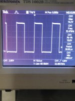
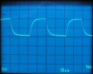
I've included two images. The first image is the power supply drive wave with no load, and the second image is the drive wave with a 47pf capacitor between the gate and source pads of the fets. In my opinion, the drivers are probably OK - but I'll put a couple fets in to try before I fit all of them just in case. I'm not a fan of substituting in class D if I can help it.
Following Perry's lead on this one could be the better route to go. I'll have the sub parts on hand just in case however.
Attachments

After waiting for over two weeks for Fedex to deliver my parts (hopefully everyone is alright due to the storms in the US!), I installed the power supply fets. I chose not to replace the drive transistors as of yet. So far, I've powered it up and checked all the waveforms - which appear to be OK. I've included them. Image one is all the gate waveforms, and image two is the drain waveforms at the power supply fets.
Before I go on, I fired up the thermal imager and put it on the board. Here is what I've found for who is heating up:
Q21 voltage regulator - gets to be about 85C - I'm assuming that since this is not clamped to the case, it's going to do that. This is not different from the last time I checked it, just wanted to note it.
Q34 power supply fet - this fet gets ~10C hotter than the rest on the same bank. All the gate resistors are within spec and the drive transistors are all cold. This bank appears to be feeding the voltage regulators.
Question is, should I replace the power supply drive transistors before high power testing? The reason I ask, is because I'd like to keep the originals in there since they are no longer available. I do have the substitute replacements on hand.
Attachments

Is there a reason why you want to keep the original drivers?
You might try testing with the replacements to see if there is any improvement. Based on the results you can choose which set to leave in the amp.
You might try testing with the replacements to see if there is any improvement. Based on the results you can choose which set to leave in the amp.
No, you're right. I'm just too paranoid since this thing keeps on going boom and I don't see it coming. Also the reason I would have liked to keep the original parts in there is simply because I'm not 100% familiar with this amp type since it's not too common in the market where I'm repairing. The original repairer already stung me with having the wrong parts in there. Without your help I would have been literally up s**t creek!
I replaced all four drivers in the power supply section. Q34 still warms up. So I replaced that fet (I bought way more than I needed so the batch was the same) and no change. I replaced the gate resistor and no change. I flipped the amp over, and there seems to be another circuit drawing from that fet. Then I remembered something that I was told when I got into repairing - get the device working, don't try to play designer to make the device work any better or less better and as long as it works as it's supposed to then leave well alone. With the amp clamped to the sink, nothing is getting to warm at all and it's working normally.
With that I put the amp back together with new thermal strips behind all the fets and regulators. I fired it up and tested on high power and all is OK. I even tested it again a second night and all is OK.
So again, thank you for your help. Your efforts are really appreciated! 🙂 🙂
- Home
- General Interest
- Car Audio
- Kicker ZX1000.1 11.29.2005