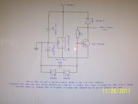
I checked the schematic and it did not match what I have. In the SX650.1 and SX1250.1 they are taking a second set of windings off the transformer. The voltage is lower so the regulator can handle it. With the SX750.1 the rail voltage, which is about 77 volts goes directly to the regulator circuit. The regulators can not handle that high a voltage reliably so they use the transistor and zeners to lower the input voltage to the regulator. The zeners bias the transistor causing it to conduct. The value of the zeners determine the input voltage to the regulator chip. I tried a 39V zener like the ones used in some models of the Fosgate amps. The input voltage to the regulator went to 40V. That's still a little high for the regulator which specs at a high of 35V on the input. I then tried 2 of the 39V zeners in series and the input to the regulator jumped to about 60V. So, I assume, if I zener it at about 30V the input to the regulator would be about right. What they are probably doing is using 2 15V zeners in series for current handling. I suspect the diode across the input and output voltages to be a zener also. I don't have a clue to the value. If the diode is left out of the circuit the input to the regulator jumps to about 67V. I ran out of time yesterday so I will try 2 15V zeners today and post the results.
Okay, I tried 2 13V zeners and the -12 supply ran correctly. This was with C44, 16V cap, out of the circuit because I blew it up with the first test. This is what I suspect they are using. Since C44 is a 16V cap and assuming no one else has been in the circuit, I believe the 2 zeners in series to be 7.5V zeners. This will run the input of the regulator at around 20 volts. I think you can use any value zeners as long as the input voltage to the regulator is within range. You will have to change C44 and maybe C36 to compensate for the voltage increase if you raise the value of the zeners.
I hope this helps someone else.
Any corrections or comments are appreciated.
Thanks to FCruze and Perry for trying to help!
I hope this helps someone else.
Any corrections or comments are appreciated.
Thanks to FCruze and Perry for trying to help!
Attachments
Something is not right here.I see it says SX750.1 on the board,but SX amps had DSP,and this doesn't.Also SX amps PCBs were blue.This looks like KX1200.1
Hi Mr. Guru, FCruz sent me a diagram of a KX1200.1. It's not the amp I was asking about. The amp was sent to me. I opened it up and checked it out. It says SX750.1 0n the board and on the end cap of the amp. It has the snap on cover on the top of the amp. I'm sure you know the type I'm talking about. The cover snaps into the heat sink on each side.
Thanks for replying.
Thanks for replying.
What I am saying is you have some old prototype.We have never had amp like that in production as i recall.It doesn't match any of the production schematics for KX amps,and SX were DSP amps.
- Status
- Not open for further replies.
- Home
- General Interest
- Car Audio
- Kicker SX750.1