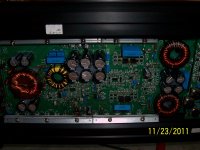
Anyone know the part number or value of D9 and D10. They are both dual diodes soldered in series. They are in the +15 and -15 volt supplies. Once again this is a Kicker SX750.1
Thanks
Thanks

Are they defective?
If they're connected between the base of the regulator's pass transistor and ground, they're likely equal to a 15 or a 16v zener. They may have used two of them if a single diode was overheating (and possibly falling off of the board).
The user carampsguru could probably tell you definitively what they are.
Yes, they are both shorted and possibly the transistor also. I'm not going any deeper into the amp until I find out what the diodes are. No need if I can't get them.
Should I send carampsguru a message or wait for him to read the post?
fcruz, I don't know if the SX650.1 would use the same diodes. If you would send the diagram I will check it out.
Thanks to both for your time and trouble.
Should I send carampsguru a message or wait for him to read the post?
fcruz, I don't know if the SX650.1 would use the same diodes. If you would send the diagram I will check it out.
Thanks to both for your time and trouble.
I don't think that carampsguru visits often. It has taken a while for him to reply when I've sent him PMs in the past.
Did you check the connections I described to see if they were connected that way?
Do the emitters of the regulator transistors connect directly to the power supply pins of the audio op-amps?
Did you check the connections I described to see if they were connected that way?
Do the emitters of the regulator transistors connect directly to the power supply pins of the audio op-amps?
That circuit doesn't look right. Did you double-check the connections?
Did you remove the shorted components before you drew the diagram? I'm assuming that you used your meter to confirm the connections and the shorted components would have made it confusing.
Did you remove the shorted components before you drew the diagram? I'm assuming that you used your meter to confirm the connections and the shorted components would have made it confusing.
I pulled the components off the board and drew the diagram by tracing from component to component. The double diodes are both shorted. The TIP30C is open and the -12V reg is shorted. These were checked out of the circuit.
I triple checked the wiring. This is correct as I see it. The diodes could be zeners. There's no markings on them. Just a blue band.
I triple checked the wiring. This is correct as I see it. The diodes could be zeners. There's no markings on them. Just a blue band.
fcruz, The SX650.1 might be the closest to the SX750.1 if you don't mind just email to RJohns777@yahoo.com
Thanks
Thanks
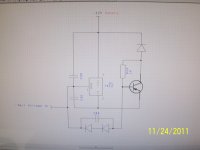
Boy is my face red. I was in a hurry yesterday because we were going to the families. I checked again and I did make a mistake. Sorry! I followed the trace for the minus rail on the bottom of the board to a cap. When I turned the board over, you guessed it, I picked up on the other lead of the cap. Again sorry! Here's the corrected diagram.
Attachments

Are you sure that the collector/emitter connections of the TIP30 are correct. They appear reversed.
Would that then put the top diode across the input and output pins of the 7915?
Would that then put the top diode across the input and output pins of the 7915?
Okay. I'm sitting here with the amp in front of me.
The minus rail voltage goes directly to pin 2 of the tip30c (collector) and to the anode of the single diode D12. There's nothing wrong with D12. It then goes through the 1 K resistor to pin 1 of the tip30c (Base). The cathode of D12 goes directly to the negative of C38 and to the -12V output. The -12V output goes directly to the op amps. Pin 3 of the tip30c (emitter) goes directly to pin 2 of the kia7912P, -12V regulator. Pin 1 of the tip30c continues to the dual diodes which then go to ground. Pin 1 of the 7912 goes to ground and pin 3 goes to the -12V output.
This has been checked with the components off the board and verified with a meter. The board is silk screened with the layout and number of each component. It's clearly marked with the direction of the diodes. There's nothing in the way to hamper the view. I checked each as I typed it into this reply. I know D12 looks funny across the input and output and I have no clue it's purpose. But it is there. It's the same on the +12V supply on the opposite side of the board.
Thank you very much for your time and trouble.
- Status
- Not open for further replies.
- Home
- General Interest
- Car Audio
- Kicker SX750.1