Correction I'm working two threads at the same time. Your amp uses a TL494. It wouldn't hurt to have the part on hand but probably won't be needed. I will get back to you tommorow
Other than the gate resistors, Q05, Q11,mosfets,U01-TL494 that is the entire circuit, short of R21,R27-47Kohm which you know to be good already. R14,R15-220 ohm if they are out of value. It wouldn't hurt to have some 1N4148's for D03,D04 on hand.
It's hard to know what else you may need until you have the power supply operational, although you should check all of the output mosfets IRF640's(two banks of six) and IRF9640's( two banks of four) and have them on hand. If one in a bank is shorted you will won't to replace the entire bank. As with the Power Supply mosfets it's recommended to be from the same batch. Having more then you need on hand is also a good idea, in case something goes awry!
It's hard to know what else you may need until you have the power supply operational, although you should check all of the output mosfets IRF640's(two banks of six) and IRF9640's( two banks of four) and have them on hand. If one in a bank is shorted you will won't to replace the entire bank. As with the Power Supply mosfets it's recommended to be from the same batch. Having more then you need on hand is also a good idea, in case something goes awry!
D03,D04 - tested with diode setting (in circuit) - came back with same value so im assuming they are good. (.58 V) since it seems like only one side of the power stage was damaged. am i wrong on this one?
Tested between 1-2 2-3 1-3 on all output stage mosfets (in circuit) - all values were identical between 9640s and all values were identical between 640s. just got my 47R0 resistors in the mail along with the 3205s. still need to order the driver transistors
the 220 ohm resistors were ~218 ohms
Tested between 1-2 2-3 1-3 on all output stage mosfets (in circuit) - all values were identical between 9640s and all values were identical between 640s. just got my 47R0 resistors in the mail along with the 3205s. still need to order the driver transistors
the 220 ohm resistors were ~218 ohms
Last edited:
Also for the irf640 - there is an 18A one and a 3.3A one available from mouser... im guessing the 18A.
replaced gate resistors -
1-3 and 1-2 for q6, q7, q8, q9 and q17 are all ~46K now.
The other bank was already aat ~46K. gonna leave those resistors alone.
just need to get the two driver transistors now
replaced gate resistors -
1-3 and 1-2 for q6, q7, q8, q9 and q17 are all ~46K now.
The other bank was already aat ~46K. gonna leave those resistors alone.
just need to get the two driver transistors now
Here are two links for the Output Mosfets from Mouser, below.
When you check the output mosfets with an ohmmeter, what are the values across the outside leads 1-3? IRF640 should be 33Kohm-IRF9640 should be 25Kohm
I misspoke in a previous thread #23. I meant to type IRF640's (two banks of three)
Everything looks good. Once you replace Q05 and Q11 you can check the drive without the IRF3205's installed.
IRF640NPBF Infineon Technologies | Mouser
IRF9640PBF Vishay Semiconductors | Mouser
Okay, so the output mosfets should be okay. It wouldn't hurt to have some on hand, just in case.
Ok, got q05 and q11 installed. Power Mosfets are NOT installed and resistances look good from pins 1-3. Ready to check the drive from Pins 9 & 10 of U01-TL 494. Awaiting further instruction.
Power up the amp. With your scope grounded to the Battery Ground terminal. With the scope probe, check the waveform's at U01-TL494 Pin 5(triangle wave) Pins 9&10(Rectangle wave). Post screen shots. follow the rectangle wave to the 47 ohm gate resistors(Mosfet side) Post screen shots from either side.
I recommend you list what soldering iron,power supply,meter and scope you have in your sig line, so anyone can easily see what you have to work with and can instruct you accordingly.
I recommend you list what soldering iron,power supply,meter and scope you have in your sig line, so anyone can easily see what you have to work with and can instruct you accordingly.
By follow the rectangle wave to the 47 ohm gate resistors you mean check the waveform at the gate resistors on the mosfet side?
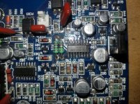
In the photo it's in the top right hand corner. This IC has a bar or stripe denoting the top of the IC. The pins run in a counterclockwise manner. Example below
1.-------- 12
2. 11
3. 10
4. 9
5. 8
6. 7
I'm on my phone, but I hope you get the idea.
1.-------- 12
2. 11
3. 10
4. 9
5. 8
6. 7
I'm on my phone, but I hope you get the idea.
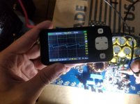

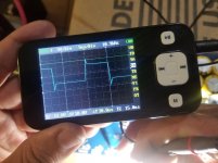
Both sides of q9 gate resistor . The bounding lines on the Y axis are +5 and -5V. the bounding lines on the X axis are -15 uS and +15uS
I had +12.4 V read by the DSP part of the amp.
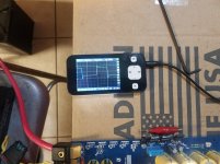
Not the best oscilloscope but it works
I had +12.4 V read by the DSP part of the amp.
Not the best oscilloscope but it works
Attachments
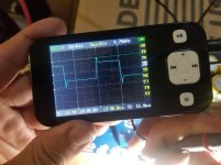
i think i checked u02 there for triangle waveform.. its the same on u01... the rectangle waveforms from u02 do not match those of u01... the ones i showed u are u01. the ones on u02 seem to have half the duration
- Home
- General Interest
- Car Audio
- Kicker sx 1250.1 burnt power transistor help