OK. If you cannot get a diagram, maybe PapaZBill can give you the progression through the op-amps so you can follow it.
Remember that the output stage also has gain (13x?). That will make the noise more significant than it is at the preamp stage.
I know that you have spent a lot of time on this so this shouldn't be too difficult. Remove the op-amp from the preamp board that's feeding the rear channels. Jump the front channel output on the preamp board to the rear channel output on the preamp board. Are the rear channel still noisier?
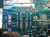
I think it's U13??? Pins from the preamp to main board labelled RL and RR connect to the RC combo then U13. So remove U13 and then jump the wires as I listed in the pic? Or just the FL to RL and FR to RR pins?
Attachments


Last edited:
This is just a guess but the LI and RI may go to feed the LM13600 and the RO/LO may be the return. I may have it backwards. It's frustrating that manufacturers won't provide diagrams when it serves no purpose to keep them under wraps.
Ok... Here's a decent trace of the circuit. Yes, it looks like LI and RI feed the 13700. So which op amp should I pull? and which pins should I jump on the connector?
Attachments
Last edited:
Pull the op-amp near the 13700. Jump the left front to the LO and the right front to the RO.
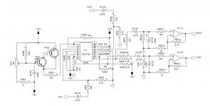
The noise is probably due to the large amount of gain required to use the LM13x00 which has a very limited input voltage. After the voltage is dropped low enough for the 13700, the gain required to restore the level is likely picking up the noise.
See attached. May be close to the LM13x00 circuit.
The noise is probably due to the large amount of gain required to use the LM13x00 which has a very limited input voltage. After the voltage is dropped low enough for the 13700, the gain required to restore the level is likely picking up the noise.
See attached. May be close to the LM13x00 circuit.
Attachments
Last edited:
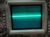
Doing what you said works. I can still hear a bit of static but I actually had to put the speaker to my ear to hear it. Sitting on the bench 1ft away I couldn't hear it. Gain pots are set all the way down. And, it's equal across all output speaker terminals. This noise might have been there the whole time. The audible noise is currently absent.
What's next?
What's next?
Attachments
Nope. A friends... what op amp you recommend? I replaced the IC 13700 with another I had in an old fusion amp. Possible both were not good? I just notied your schematic. Thanks, going to go over the circuit again, and def save it. 😉
Last edited:
I only get 2.7Kohms on both R600 and 602. The schematic says 6.2K.. should I replace them to 6.2K?
The diagram is from a similar amp. The values may not match.
Model 879B, 40,000 Count Dual Display Handheld LCR Meters - B&K Precision
If you can find a sencore LC102 in good working order for cheap, it's somewhat more capable. I have one but I always use the BK.
I don't know if low-noise op-amps come in SIP packages. You could solder 4 terminals of a DIP into the board and use ribbon cable to wire the other 4 to the board is an SIP isn't available.
If your friend doesn't use the remote, remove the coupling caps equal to C475 and C476 and the op-amp and jump the connections on the preamp board that went to/from the main board.
I doubt he would ever use it. He uses the amp for highs. So leave out the op amp, remove the 2 caps (same designation in this amp) and leave the jumpers I have from FL to L0 and FR to R0?
Now if he sells it later and someone else puts in the remote line it will just not work? No damage could come from it? If so, I'll remove the connector too, lol
I could just do the mod too... what op amp shall I try?
Thanks for the link for the meter. I'll have to scoop one up.
Now if he sells it later and someone else puts in the remote line it will just not work? No damage could come from it? If so, I'll remove the connector too, lol
I could just do the mod too... what op amp shall I try?
Thanks for the link for the meter. I'll have to scoop one up.
Last edited:
Remove those jumpers. Those were to get a known clean signal from the front input to feed the rear channels.
Jump RI/RO and LI/LO. That will leave it a 4-channel amp.
There will be no damage if a remote is used. It simply will have no effect.
Jump RI/RO and LI/LO. That will leave it a 4-channel amp.
There will be no damage if a remote is used. It simply will have no effect.
That did the job. Thank you sir! 🙂 Sooo... what exactly is causing the noise? The gain from the remote circuit?
Yes. If you look at the diagram, you can see that a 30k and 470 ohm resistor drop the signal to about 0.015 of original. They have to reverse that to get the signal back to where is was (65x). There is a lot of ground (literally and figuratively) between the input and output pins on the connector. All of that contributes noise.
Apologize for being AWOL, but life!! I compared the remote gain diagram you posted with the schematic for this amp and value for value they are identical except for R600 & R602 which are in fact 2.7kohm. If you were to swap out the two resistors for the 6.2kohm, it would increase the gain factor by 2.3, however I'm not sure this would improve your noise problem and may make it worse.
I think Perry's solution is good one,since you will not be using the remote gain, However you might try removing the header socket and cleaning it,the through holes on main board and preamp board pins with alcohol and a brush,reflowing solder on all of the solder joints for header socket and preamp board pins. You would be surprised how much just cleaning the contacts can improve the Signal to Noise.
I think Perry's solution is good one,since you will not be using the remote gain, However you might try removing the header socket and cleaning it,the through holes on main board and preamp board pins with alcohol and a brush,reflowing solder on all of the solder joints for header socket and preamp board pins. You would be surprised how much just cleaning the contacts can improve the Signal to Noise.
FYI for future googlers like myself, this site appears to have schematics for KX800.4
Service manual, eprom result list | Elektrotanya
Service manual, eprom result list | Elektrotanya
- Home
- General Interest
- Car Audio
- Kicker KX800.4 static