Good evening,
I got this amp in with the pots and switches intermittent. I cleaned them all and everything seems to work much better.
However, the "amp 2" channels have static on them. Sounds like an old analog tv when you'd have the "snowy" picture on it and that static sound.... it sounds exactly like that.
With the amp 2 Xover switch set to Off or high it's not too noticeable. On low pass however it is very noticeable. It does this even with no RCA connected.
Could it still be a bad switch or pot? I cleaned them a couple times. One half seems to be working fine... What else could it be? It does play music just a bit distorted... not as clear as the amp 1 channels.
Thanks in advance
Is it possible that there is more than one problem?
On some of the older kicker 4 channel amps, the rear channels would be noisy of there was no front channel input.
If the brown fixative is in contact with any electrical component, it needs to be removed. It becomes corrosive and conductive.
On some of the older kicker 4 channel amps, the rear channels would be noisy of there was no front channel input.
If the brown fixative is in contact with any electrical component, it needs to be removed. It becomes corrosive and conductive.
I don't recall if the Kicker 4 channel amps suffered this problem, as the 5 channel amps did. I would be curious to hear what you find.
It's possible that a bad switch or pot may need more attention or replacing. Check all pots with an ohmmeter they should all read ~20kohm one way and near zero the other.
You may need to check solder joints on opposite side of board,especially around the preamp board header socket,outputs sections and larger jumpers.
Alright back to this amp. I added front and rear RCA still has the static on both rear (amp 2) channels. I'll remove all the fixative I see.
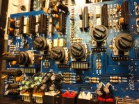
How might I go about testing these multi pin pots? Just the outside 2 connections fine? From the body to other pins? No matter what combination I try, I get 17K and about 5ohms at best. One pot reads 12K. The bigger double ones seem to be even harder to get a good reading off of. I don't test pots too often. I know they are essentially just a resistor with a wiper that adjusts its range, but not sure how these multi ones work...
Thanks
Attachments
Last edited:
If 2 channels are run through each op-amp in the circuit, a single bad op-amp could cause a problem like this. Overheating is one symptom to look for.
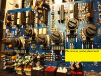
Here is the probe placement for checking the pots. You will place probes green to green and white to white seperately. The frequency pots will use the same placement top and bottom,for obvious reasons I was only able to label top side. Holding probes while rotating pots through their entire range you should see the resistance change smoothy from ~17Kohm to near zero ohms.
Attachments
This amp has a remote bass control circuit that only passes through rear channels or amp 2. You will find this circuit underneath the input board. The fixative that Perry refered to has been known to cause this circuit to fail. The circuit consists of U3-LM13700,U4-BA4558, Q1-2N4403,Q16-2N4401,Resistors,capacitors. Check all components that have fixative on them. Resistors and Caps should be check by lifting one leg out of the board.
You can remove input board and check the DC voltages around U3,U4,Q1 & Q16 and post.
If you have a way to signal trace(audio generator or test tone CD and oscilliscope) you will need to build a jumper cable so that the input board can be moved out of the way to access circuit underneath. Otherwise replacing the IC's and transistors would be an option.
Check to see if there is any DC voltage between the RCA's and speaker or power grounds.
If you havn't examined the underside of board for bad solder or blown traces you may want to do that, before you get to deep into the Remote gain circuit,
Last edited:
I haven't taken it out of the case yet. Will do when I get home and check all this stuff. I'll report back once I do. Thanks!
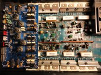
Well. There was def multiple things wrong as I was taking it out of the case I found. A rectifier D13 and output transistor Q261 had their middle legs broken. At some point someone else cut the legs and resoldered them back very poorly. I just made quick connections for now. Will replace them all once I get the static out. Also the jumpers at P45 and P48 needed resoldering.
SO, I have removed all fixative. Checked all the resistors around U3. All read OK. There is no DC (well 0.001-0.002v) between RCA shield and main ground or non-bridging speaker terminals. Also felt all the preamp op amps after leaving run for a bit, none seem to be getting warm. Not to the touch anyway.
I get the following voltages using the jumpers connecting the 2 transformers secondaries together as reference.
U3:
Pin 1: 13v
Pin 2: 0.96v
Pin 3: 0.316v
Pin 4: 0.316v
Pin 5: 0.019v
Pin 6: -14.38
Pin 7: 0.018
Pin 8: -1.15
Pin 9: -1.05
Pin 10: 0.990
Pin 11: 14.92
Pin 12: 0.997
Pin 13: 0.31
Pin 14: 0.31
Pin 15: 0.95
Pin 16: -13.14
U4
Pin 1: 0.002
Pin 2: 0
Pin 3: 0
Pin 4: -14.7
Pin 5: 0
Pin 6: 0
Pin 7: 0.001
Pin 8: 14.65
Q1: 1) 14.67 2) 14.02 3) 13.94
Q16: 1) 13.93 2) 0.003 3) 14.02
I will work on trying to find a computer cable or something I can make a jumper for the preamp card with. I do have a scope.
Last edited:
I have switched every NJM4558L in U4 on the main board, U3, U4, U10, U11, U12, U13 and U14 on the preamp card. Removed and checked Q1 and Q16.
Static is still there. Anything else it could be?
Static is still there. Anything else it could be?
Last edited:
I also found a scrap amp and pulled the LM13700D. So now I have replaced U3 and U4 on the main board. Pulled, checked and reinstalled Q1 and Q16. Removed, checked and replaced all the NJM4558's on amp 2 side of the preamp card. Even though they seemed to all test fine. Check all pots. All read around 5-8ohms low and 15-17K high.
The static is not there until the preamp card is added to the circuit.
The static is not there until the preamp card is added to the circuit.
Can you see the noise (with your scope) on the noisy channels at the connector going to the main board?
It depends on the low level noise on the board (common to virtually every circuit) and the level of the pulses of the static noise.
Do you have one of the Radio Shack mini-amps that you could use to trace the noise if you can't see it with your scope?
Do you have one of the Radio Shack mini-amps that you could use to trace the noise if you can't see it with your scope?
No sir.
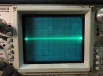
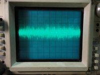
O.K. Scope set to .1v/div and 1ms I can see the static. It only appears on the L+ and R- terminals. It is not showing on any of the pins going to the main board.
Please see pics. Sorry not super clear. Scope is hard to capture noise.
O.K. Scope set to .1v/div and 1ms I can see the static. It only appears on the L+ and R- terminals. It is not showing on any of the pins going to the main board.
Please see pics. Sorry not super clear. Scope is hard to capture noise.
Attachments
Last edited:
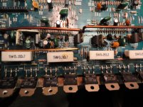
I can also see it on the 2 TIP41's and 2 TIP42's. But do not see it on Q250 or Q450
Attachments
Last edited:
- Home
- General Interest
- Car Audio
- Kicker KX800.4 static