It was a 4.7 100V electrolytic cap. Closest I had on hand was a 2.2 100V so I subbed it in to see if it would get some output. There was no output and the first time I cranked it up it popped like a firecracker.
C211 is a 4.7uF 100v electrolytic NP (Non Polarized) capacitor. This is part of the Class D output filter and Same varying DC component is present. You should be able to continue testing without a cap at C211.
You can check the relay by power up w/o signal and using an ohmmeter across the contacts. You should see a high reading with no power and near 0 ohms when powered up and after relay clicks.
When you apply signal do you see AC on output side of L212?
You can check the relay by power up w/o signal and using an ohmmeter across the contacts. You should see a high reading with no power and near 0 ohms when powered up and after relay clicks.
When you apply signal do you see AC on output side of L212?
I'm assuming L212 is the large output inductor, as I can't see its designation on my amp due to the glue. I'm not sure which side to measure from, but either side seems about the same. With full gain it reads ~50V AC varying about 5-10V, and with gain all the way down about 10V AC varying a few volts.
Had some chores to get done but finally pulled the board out of the chassis and checked the relay and...... its bad. Pulled it from the board and jumpered across it and got sound on the output.
It looks like I need to replace the NP cap and the relay and I'll have it back up and running. Thanks for all the help. Rock On!
It looks like I need to replace the NP cap and the relay and I'll have it back up and running. Thanks for all the help. Rock On!
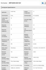
So searching around the relay number doesn't come up on any of the reliable distributors. Can anyone recommend an equivalent for the HR702HH relay available from Mouser or Digikey?
.... Can anyone recommend an equivalent for the HR702HH relay available from Mouser or Digikey?
I see HR702HH-DC12V on Aliexpress and here is a data sheet: HR702HH-DC12V | P.C. Board Power Relay (HR702) | HANKUK RELAY | MISUMI Vietnam
The HR702HH-DC12V coil current is 30mA and SPST contact is 15A, size: 19mm x 16mm x 15mm
Here is one option but it pulls more coil current (66.7 mA), Omron G4W-1112P-VD-TV8 DC12 : https://www.mouser.com/ProductDetai...112P-VD-TV8-DC12/?qs=JK6Bpmia/mubzwTj8fSbkQ==
Omron G4W-1112P-VD-TV8 DC12 Datasheet (PDF)
The Omron size is different and the pins likely will not line up on the PCB.
Here is another one, but not much info: Omron G5CA6001R: https://www.digikey.com/en/products/detail/omron-electronics-inc-emc-div/G5CA6001R/13673243
This one may not fit size wise (75mA coil), Omron LY1-0-DC12 Power Relay, SPDT, 12 VDC, 15 A, LY Series, PCB, Non Latching: https://www.newark.com/omron-industrial-automation/ly1-0-dc12/relay-spdt-240vac-30vdc-15a/dp/35K3203
Attachments
Thanks guys, I was googling in circles and not coming up with much. Based on the specs you found for the relay I searched and Digikey has the AZ943-1AH-12DE. It looks like a drop in replacement. I'll get a couple ordered in, as well as the NP capacitors. I figure I'll go ahead and replace both caps in that part of the circuit for good measure.
PapaZBill, you seem quite the expert on these, any other recommendations while I'm in there and needing to get a minimum order together?
PapaZBill, you seem quite the expert on these, any other recommendations while I'm in there and needing to get a minimum order together?
I might've fixed one or two in my time at Kicker.
There really isn't anything else you'll need. It appears the amp is in good working order.
There really isn't anything else you'll need. It appears the amp is in good working order.
Order done! 0.78$ for two relays, 15$ to ship them direct from manufacturer.
Thanks again all, for the help.
Thanks again all, for the help.
I might've fixed one or two in my time at Kicker.
There really isn't anything else you'll need. It appears the amp is in good working order.
Well, 20 miles from Stillwater.
did you work on one these...
Attachments

I may have worked on the Amps, yes. I run the ER Department now, so I make other people work on amps! [emoji41]
Round 2?
I got the relay and capacitors in, and installed in the amp. Didn't have the relay clicking anymore. Ended up replacing the transistor that engages the relay (Q75) on the perpendicular bard near the SMPS chip. Not easy by the way, but now the relay is working and passing audio when engaged. However after about two seconds the relay shuts back off. For the ~2 seconds before the shutdown, I get output on the sub channel.
Amp is still not in protection. Green LED stays lit and rail voltages are present. When connected to power the relay clicks in and after you connect the enable line, it takes about 2 seconds to power it off. I do see the voltage climbing on pin 3 of the SMPS chip as soon as you power up the enable line and goes up to 11V, by 7V it shuts down the relay.
I'm not sure what criteria are being considered to disable the output since its not in protection. Any light that could be shed on the subject would be appreciated.
A bit of an update after tinkering with it a bit more this evening. I noticed that dead cold the sub channel will power on and play for about 15 seconds before the relay cuts out. Cycle power and it played about 8 seconds, again maybe 5 seconds, until finally 2 seconds consistently before cycling the relay off. I popped the class D board out but it still cycles off the relay just the same. It seems that something is heating up but there isn't anything obviously getting hot.
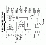
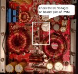
Check the DC Voltages around U01-TL494 on PWM card. Also the DC voltages on the pins of the PWM card. Use Power GND for black probe. Also monitor voltage on the collector of Q75-3876GR from power up.
Do you have uninterrupted audio on Amps 1 & 2?
Do you have uninterrupted audio on Amps 1 & 2?
On the TL 494 I get DC 4.8, 4.7, 11.8, 12.7, 4.9, 4.9, 4.9, 0, 11.8, 0, 3.7, 1.4, 0(transformer hiss when measuring), 0, 4.9, 0
On the class D board I have 5.9 on SIMK with +12, -12, and 0 respectively.
Q75 sits around 3V on standby and ramps to 11V once enabled.
I do have audio on amp 1 and 2
Wanted to ask, what type of transistor is Q75? I cross ref'd to a PNP, but your number looks like an NPN according to google
On the class D board I have 5.9 on SIMK with +12, -12, and 0 respectively.
Q75 sits around 3V on standby and ramps to 11V once enabled.
I do have audio on amp 1 and 2
Wanted to ask, what type of transistor is Q75? I cross ref'd to a PNP, but your number looks like an NPN according to google
Last edited:
On the TL 494 I get DC 4.8, 4.7, 11.8, 12.7, 4.9, 4.9, 4.9, 0, 11.8, 0, 3.7, 1.4, 0(transformer hiss when measuring), 0, 4.9, 0
Please list the voltages above in this format. Otherwise it's hard to decipher.
U01-TL494
Pin 1
Pin 2
Pin 3
etc
PDF attached for the KTC3876GR NPN Transistor
Please list the voltages above in this format. Otherwise it's hard to decipher.
U01-TL494
Pin 1
Pin 2
Pin 3
etc
PDF attached for the KTC3876GR NPN Transistor
Attachments
See Attachment.
There are 5 or 6 pins on the soft start card (I mistakenly called this the PWM card). Measure each one after power up. One of the pins will be the soft start voltage. When monitoring this pin from power up, you should see the voltage ramp up and then latch at about 12V dc.
What I'm thinking is the soft start is not latching, and the relay turn on voltage at Q75 is fluctuating. I not sure this is the issue, but want to rule it out.
Posting all measurements as I suggested in for this and the U01-TL494 will give me a better picture of what is happening. As Perry mentioned there is some confusion with your post. Pin 3 of the TL494 is not connected and Pin 4 makes more sense.
Attachments
Last edited:
- Home
- General Interest
- Car Audio
- Kicker KX700.5 No sub after low battery.