Amp powers up but they relay keeps clicking on and off over and over again..
When the relay clicks on and off and on and off the protection light flashes every time the amp clicks on and off..
Anyone have any ideas ?
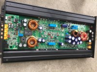
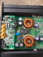
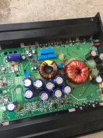
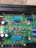
The fan was removed for the pics
When the relay clicks on and off and on and off the protection light flashes every time the amp clicks on and off..
Anyone have any ideas ?
The fan was removed for the pics
Attachments
At a time when the relay closes, measure if to the output speaker terminal there is substancial DC.
it is likely that one of the two amplification stages has one or more mosfet in short, or there is a problem on the driver circuit.
If I were you, I'd do it step by step, partly because we do not have the schematic.
I would check individually all output MOSFET, but to do this, you have to remove them all from the board.
No need to check the power stage, because if the amplifier comes on, it means that the power supply works well.
After removing all output mosfet, also need to check if the power supply sends out all the required voltages, such as rail +/-, +/- low voltages for the driver stage and the preamplifier.
Make these tests and write the results here.
You shouldn't have to remove output mosfets.
Check in circuit,power removed with an ohm meter. Good mosfets will read in the Kohm or Meg ohm,middle to outside leads. Outside leads will read 33kohm on the IRF640'S and 22kohm on the IRF9640'S.
It's common for an IRF640 to short less then 10 ohms.You may find shorted IRF640'S
When you find a shorted output,remove only the shorted mosfet and continue troubleshooting.If necessary I will post the resistor that can be removed to disable protection (I'll need to check notes at work)
Sent from my SAMSUNG-SM-G870A using Tapatalk
Thanks .. no outputs are shorted or leaky already checked them
..
Something else is causing the issue but can't pin point it at the moment ..
..
Something else is causing the issue but can't pin point it at the moment ..
Left R22. Monitor current draw if you can. If draw is excessive shutdown amp. Do you have an O-scope?
Sent from my SAMSUNG-SM-G870A using Tapatalk
Sent from my SAMSUNG-SM-G870A using Tapatalk
When you power amp up after lifting R22, do you see anything at the output filter inductors?
Sent from my SAMSUNG-SM-G870A using Tapatalk
Sent from my SAMSUNG-SM-G870A using Tapatalk
There are two IC's that have their markings scratched off. The one with the crystal (blue in color) is an MC14060BG-14 bit Binary Counter. The other is an LM361-Comparator that make up the Class D circuit. I believe the LM361 is U14.
Measure the DC volts around U14 and the MC14060 and post. Using the Negative Spkr terminal for the black probe and post results.
With your scope and using the same reference check the waveform at Pin 4, Pin 9 and Pin 11 of U14. If you don't have a Triangle wave on Pin 4 check the MC14060.
If the Triangle looks rounded off on the positive peak and no square wave on Pin 11, Jumper Pin 3 U14 to ground.There is a sm cap (1206) on the same side of Pin 3 which will be a good place to tack solder the jumper. The jumper will ground the input signal and if U14 is good the triangle wave will look clean and you will have output on pin 9 & Pin 11(Pin 9 is not connected).
I have one of these amps mine was doing the same thing after changing the lm361 which was visibly damaged. Mine was one of the driver transistors for the output. Try checking Q301,Q321,Q201,Q221. If I remember correctly their 2-A1381's & 2-C3503's.
Correction:There are two IC's that have their markings scratched off. The one with the crystal (blue in color) is an MC14060BG-14 bit Binary Counter. The other is an LM361-Comparator that make up the Class D circuit. I believe the LM361 is U14.
Measure the DC volts around U14 and the MC14060 and post. Using the Negative Spkr terminal for the black probe and post results.
With your scope and using the same reference check the waveform at Pin 4, Pin 9 and Pin 11 of U14. If you don't have a Triangle wave on Pin 4 check the MC14060.
If the Triangle looks rounded off on the positive peak and no square wave on Pin 11, Jumper Pin 3 U14 to ground.There is a sm cap (1206) on the same side of Pin 3 which will be a good place to tack solder the jumper. The jumper will ground the input signal and if U14 is good the triangle wave will look clean and you will have output on pin 9 & Pin 11(Pin 9 is not connected).
The LM361 is U508 and the 14060 is U509.
Sent from my SAMSUNG-SM-G870A using Tapatalk
- Status
- Not open for further replies.
- Home
- General Interest
- Car Audio
- Kicker KX1200.1