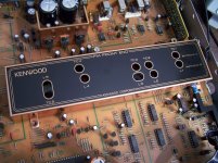
So I started checking the alignment of my Kenwwod KT-3300D tuner.
I'm practicing on my spare unit first to make sure everything goes ok and I have marked off all pots and coils with a sharpie just to make sure.
For the most part, everything so far is going good and I can see actual changes in my adjustments on the scope, distortion meter and ac/dc meter.
On the alignment sheet that I attached to this post, items 5, 6, and 7 are causing me some grief as I can't seem to notice any changes on my scope when making adjustments which is leading me to think that perhaps I'm doing something wrong.
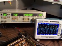
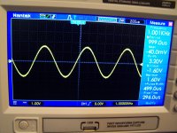
Attached is a picture of my scope display showing the 1 kHz output at the RCA outs as per the alignment procedure.
Can anybody explain why any changes to the coils are not affecting my output reading?
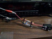
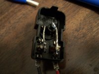
One thing I will mention is that on the 3rd attached alignment page, it shows a picture of a 300 to 75 ohm antenna adapter and what they call a dummy antenna. I'm not sure what a dummy antenna is but what I did is I gutted the 300 to 75 ohm adapter and connected the center pin direct to one of the screws and the outer ground shield direct to the other screw which is connected to a 50 to 75 ohm resistive pad to the generator. I assume that would be the correct way to do this?
Thanks!
I'm practicing on my spare unit first to make sure everything goes ok and I have marked off all pots and coils with a sharpie just to make sure.
For the most part, everything so far is going good and I can see actual changes in my adjustments on the scope, distortion meter and ac/dc meter.
On the alignment sheet that I attached to this post, items 5, 6, and 7 are causing me some grief as I can't seem to notice any changes on my scope when making adjustments which is leading me to think that perhaps I'm doing something wrong.
Attached is a picture of my scope display showing the 1 kHz output at the RCA outs as per the alignment procedure.
Can anybody explain why any changes to the coils are not affecting my output reading?
One thing I will mention is that on the 3rd attached alignment page, it shows a picture of a 300 to 75 ohm antenna adapter and what they call a dummy antenna. I'm not sure what a dummy antenna is but what I did is I gutted the 300 to 75 ohm adapter and connected the center pin direct to one of the screws and the outer ground shield direct to the other screw which is connected to a 50 to 75 ohm resistive pad to the generator. I assume that would be the correct way to do this?
Thanks!
Attachments
Last edited:
A dummy antenna is a small network of components which roughly mimic the impedance of a real antenna, while providing a place to attach a signal generator. They sem to assume that the sig gen will be 300 ohms - unlikely nowadays, but may have been common in some countries a while ago. (I heard recently that the Netherlands used 300R twin feeder for TV and FM until the 1970s)
I don't understand their instructions for 5, 6 and 7. I would not expect to see any change in the audio output as you adjust the RF alignment - so you are seeing exactly what I would expect. Does it have a signal strength meter? If so, adjust for maximum reading on this. Ignore the audio output. You will need to repeat 5 and 6 as the adjustments interact with each other.
I don't understand their instructions for 5, 6 and 7. I would not expect to see any change in the audio output as you adjust the RF alignment - so you are seeing exactly what I would expect. Does it have a signal strength meter? If so, adjust for maximum reading on this. Ignore the audio output. You will need to repeat 5 and 6 as the adjustments interact with each other.
Thanks for the info!
I will be trying to get as much info as I can over the next week or so and then try it again to see if I can see some results.
Im not sure why they show a 300 to 75 ohm adaptor.
What I did with mine is I gutted the adaptor and connected the centre pin directly to one of the screws and the outer ground/shield directly to the other screw. The output of my generator is 50 ohms so I made 50 to 75 ohm resistive pad which then connects directly to the screws of the adaptor. Due to the losses of the pad, I have to multiply the output of the generator by 1.55.
Does this sound correct?
I suspect they show a 300-75 adaptor because they assumed that people would use a 300 ohm dummy antenna. Your 50-75 pad will be sufficient for reasonable alignment. No need for the modified adaptor.
I suspect they show a 300-75 adaptor because they assumed that people would use a 300 ohm dummy antenna. Your 50-75 pad will be sufficient for reasonable alignment. No need for the modified adaptor.
Well that makes perfect sense.
That must be what the dummy antenna is........a 50 to 300 ohm matching pad to match with the 300 to 75 ohm adaptor
Roughly. Some dummy antennas may make an attempt to simulate the impedance and frequency response of a real antenna, but many do not. Basically, the more closely the dummy antenna presents an impedance like a real antenna, the more your RF alignment will match normal use. However, the dummy antenna cannot know which real antenna you will be using so even at best it is a crude approximation.
That tuner has very low distortion (was the top Kenwood in the mid eighties) , on the 3nd picture they show distortion analyzers as an example, maybe your oscilloscope not good enough to measure any distortion changes when you making the adjustments.
So I'm having a little difficulty with some of these alignments and need some help from you experts.
I followed the suggestions that you guys made about lowering the output of the generator for alignment # 5 and 6 to the point that I see noise on the scope but even with drastic changes to the coils, seen very little changes on the scope. I did notice some changes to the strength meter display however even though they were small, I did peak for maximum on the meter display so I guess that's the best that can be done with that.
One of the problems I'm still trying to make sure that I'm getting right is the generator output settings.
Alignment # 7, 8, and 9 call for very low output of the generator.
# 7 calls for 2 - 3 dbu, # 8 calls for 12 dBu and # 9 calls for 43 dBu.
My generator outputs in dBu EMF so I have been using the following converter.....
https://www.eeweb.com/tools/rf-unit-converter
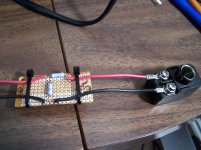
Attached are some pics of how I have my generator connected to my tuner. As you can see, I gutted and modified the 300 ohm to 75 ohm adaptor which is connected to a resistive 50 ohm to 75 ohm matching pad that is connected to the 50 ohm output of my generator using a 50 ohm BNC cable. I then need to adjust the generator output voltage to 1.55 times due to the losses in the resistive pad which I constructed from this site....... http://ham-radio.com/k6sti/match.htm
So for example, alignment # 9 calls for 43 dBu (Ant Input). According to the converter tool, 43 dBu equals 141 uV. If I multiply the 141 x 1.55= 218.55 uV.
Now if I place that 218.55uV into the uV box in the converter, the dBuV has now changed to 46.8 and the dBu EMF box is now showing 52.8. So the 52.8 dBu EMF is what I'm setting my generator for.
Same thing applies to alignment # 7 and # 8..... I use the same procedure for calculating the output of my generator for all settings ....... but yet # 7 and # 8 don't seem to have enough output to get any results.
Checking the IFT as in procedure # 7 made absolutely no changes to the scope display when adjusting the coils. I even tried using the level input of my distortion meter with no change so now I'm getting frustrated with the possibility that I'm doing something wrong.
Can anybody tell me if I'm doing this right? I need to know if I'm doing something wrong using the above online converter for these alignments cause if I don't have the correct Ant Input, then I can't accurately adjust # 8 for the stereo light and # 9 for the signal meter display.
I did manage to figure out # 10 and most of the other settings after but I do have another question.
Using # 10 as an example, it ask for an input setting of 10Hz 100-150kHz dev.
I don't believe that I can set my FM generator for a frequency other then the internal 1 kHz or 400 H signal which means that I need to feed an external 10 Hz signal into it which I did from another generator. My FM generator modulation can only be set from 0 to 100 dev so I'm not sure how I'm suppose to get 100-150 kHz dev. Am I missing something??
Any help would be greatly appreciated!
I followed the suggestions that you guys made about lowering the output of the generator for alignment # 5 and 6 to the point that I see noise on the scope but even with drastic changes to the coils, seen very little changes on the scope. I did notice some changes to the strength meter display however even though they were small, I did peak for maximum on the meter display so I guess that's the best that can be done with that.
One of the problems I'm still trying to make sure that I'm getting right is the generator output settings.
Alignment # 7, 8, and 9 call for very low output of the generator.
# 7 calls for 2 - 3 dbu, # 8 calls for 12 dBu and # 9 calls for 43 dBu.
My generator outputs in dBu EMF so I have been using the following converter.....
https://www.eeweb.com/tools/rf-unit-converter
Attached are some pics of how I have my generator connected to my tuner. As you can see, I gutted and modified the 300 ohm to 75 ohm adaptor which is connected to a resistive 50 ohm to 75 ohm matching pad that is connected to the 50 ohm output of my generator using a 50 ohm BNC cable. I then need to adjust the generator output voltage to 1.55 times due to the losses in the resistive pad which I constructed from this site....... http://ham-radio.com/k6sti/match.htm
So for example, alignment # 9 calls for 43 dBu (Ant Input). According to the converter tool, 43 dBu equals 141 uV. If I multiply the 141 x 1.55= 218.55 uV.
Now if I place that 218.55uV into the uV box in the converter, the dBuV has now changed to 46.8 and the dBu EMF box is now showing 52.8. So the 52.8 dBu EMF is what I'm setting my generator for.
Same thing applies to alignment # 7 and # 8..... I use the same procedure for calculating the output of my generator for all settings ....... but yet # 7 and # 8 don't seem to have enough output to get any results.
Checking the IFT as in procedure # 7 made absolutely no changes to the scope display when adjusting the coils. I even tried using the level input of my distortion meter with no change so now I'm getting frustrated with the possibility that I'm doing something wrong.
Can anybody tell me if I'm doing this right? I need to know if I'm doing something wrong using the above online converter for these alignments cause if I don't have the correct Ant Input, then I can't accurately adjust # 8 for the stereo light and # 9 for the signal meter display.
I did manage to figure out # 10 and most of the other settings after but I do have another question.
Using # 10 as an example, it ask for an input setting of 10Hz 100-150kHz dev.
I don't believe that I can set my FM generator for a frequency other then the internal 1 kHz or 400 H signal which means that I need to feed an external 10 Hz signal into it which I did from another generator. My FM generator modulation can only be set from 0 to 100 dev so I'm not sure how I'm suppose to get 100-150 kHz dev. Am I missing something??
Any help would be greatly appreciated!
Attachments
-
KT-3300D Adustment3.pdf440.2 KB · Views: 89
-
KT-3300D Adustment2.pdf556.6 KB · Views: 95
-
KT-3300D Adustment1.pdf857.5 KB · Views: 96
-
 100_8537.JPG910 KB · Views: 144
 -
 100_8536.jpg474.3 KB · Views: 106
 -
 100_8533.JPG745.2 KB · Views: 103
 -
 100_8506.JPG740 KB · Views: 176
 -
 100_8505.JPG786.9 KB · Views: 184
So I'm having a little difficulty with some of these alignments and need some help from you experts.
I followed the suggestions that you guys made about lowering the output of the generator for alignment # 5 and 6 to the point that I see noise on the scope but even with drastic changes to the coils, seen very little changes on the scope. I did notice some changes to the strength meter display however even though they were small, I did peak for maximum on the meter display so I guess that's the best that can be done with that.
Is there any description in the documentation about measuring the IF level with a scope? That could be rather more accurate, if you know how to connect the scope without affecting the circuitry too much.
One of the problems I'm still trying to make sure that I'm getting right is the generator output settings.
Alignment # 7, 8, and 9 call for very low output of the generator.
# 7 calls for 2 - 3 dbu, # 8 calls for 12 dBu and # 9 calls for 43 dBu.
My generator outputs in dBu EMF so I have been using the following converter.....
https://www.eeweb.com/tools/rf-unit-converter
Attached are some pics of how I have my generator connected to my tuner. As you can see, I gutted and modified the 300 ohm to 75 ohm adaptor which is connected to a resistive 50 ohm to 75 ohm matching pad that is connected to the 50 ohm output of my generator using a 50 ohm BNC cable. I then need to adjust the generator output voltage to 1.55 times due to the losses in the resistive pad which I constructed from this site....... Matching 50Ω to 75Ω
So for example, alignment # 9 calls for 43 dBu (Ant Input). According to the converter tool, 43 dBu equals 141 uV. If I multiply the 141 x 1.55= 218.55 uV.
Now if I place that 218.55uV into the uV box in the converter, the dBuV has now changed to 46.8 and the dBu EMF box is now showing 52.8. So the 52.8 dBu EMF is what I'm setting my generator for.
Same thing applies to alignment # 7 and # 8..... I use the same procedure for calculating the output of my generator for all settings ....... but yet # 7 and # 8 don't seem to have enough output to get any results.
For the FM tuners of early 21st century car radios, the levels are usually specified in dBuV RMS equivalent dummy antenna input level, with the dummy antenna defined such that this is the same as dBuV RMS EMF. In that case, the level indicated by your generator would simply be the correct level, no need to convert anything. But how this was done by Kenwood decades ago, I really don't know. For example, suppose it is dBuV EMF, is that referred to 75 ohm or to 300 ohm?
You could try measuring the stop level on a Kenwood tuner that works well and that you haven't touched, if you have or can borrow one. Maybe you can then reverse engineer what was meant by comparing the stop level with the 12 dBuV spec. By the way, the document seems to imply that switching to stereo is done at the same level as stopping the automatic search, I haven't a clue why they chose the same level for both.
As an alternative for adjustments 8 and 9, you could ignore the spec and adjust for a stop level that you like (the automatic search should stop for any station that is strong enough to listen to) and for a level display that you like.
For adjustment 7, the point is probably that the signal should be small enough not to be hard clipped by limiter stages. That means using the smallest level that still produces a recognizable signal on the scope. I expect that the scope has to be connected to some IF test point, though.
Checking the IFT as in procedure # 7 made absolutely no changes to the scope display when adjusting the coils. I even tried using the level input of my distortion meter with no change so now I'm getting frustrated with the possibility that I'm doing something wrong.
Like I wrote, I expect you have to measure at IF. If there a description how to do that anywhere? If not, have you got a schematic of the tuner so we can try to reverse engineer it?
Can anybody tell me if I'm doing this right? I need to know if I'm doing something wrong using the above online converter for these alignments cause if I don't have the correct Ant Input, then I can't accurately adjust # 8 for the stereo light and # 9 for the signal meter display.
I did manage to figure out # 10 and most of the other settings after but I do have another question.
Using # 10 as an example, it ask for an input setting of 10Hz 100-150kHz dev.
I don't believe that I can set my FM generator for a frequency other then the internal 1 kHz or 400 H signal which means that I need to feed an external 10 Hz signal into it which I did from another generator. My FM generator modulation can only be set from 0 to 100 dev so I'm not sure how I'm suppose to get 100-150 kHz dev. Am I missing something??
Any help would be greatly appreciated!
You could maybe manually modulate the generator. Switch off its modulation and manually switch its carrier between 97.9 MHz and 98.1 MHz while the tuner is tuned to 98 MHz. In both cases it should indicate with equal brightness that the tuning is not good.
Is there any description in the documentation about measuring the IF level with a scope? That could be rather more accurate, if you know how to connect the scope without affecting the circuitry too much.
For the FM tuners of early 21st century car radios, the levels are usually specified in dBuV RMS equivalent dummy antenna input level, with the dummy antenna defined such that this is the same as dBuV RMS EMF. In that case, the level indicated by your generator would simply be the correct level, no need to convert anything. But how this was done by Kenwood decades ago, I really don't know. For example, suppose it is dBuV EMF, is that referred to 75 ohm or to 300 ohm?
You could try measuring the stop level on a Kenwood tuner that works well and that you haven't touched, if you have or can borrow one. Maybe you can then reverse engineer what was meant by comparing the stop level with the 12 dBuV spec. By the way, the document seems to imply that switching to stereo is done at the same level as stopping the automatic search, I haven't a clue why they chose the same level for both.
As an alternative for adjustments 8 and 9, you could ignore the spec and adjust for a stop level that you like (the automatic search should stop for any station that is strong enough to listen to) and for a level display that you like.
For adjustment 7, the point is probably that the signal should be small enough not to be hard clipped by limiter stages. That means using the smallest level that still produces a recognizable signal on the scope. I expect that the scope has to be connected to some IF test point, though.
Like I wrote, I expect you have to measure at IF. If there a description how to do that anywhere? If not, have you got a schematic of the tuner so we can try to reverse engineer it?
You could maybe manually modulate the generator. Switch off its modulation and manually switch its carrier between 97.9 MHz and 98.1 MHz while the tuner is tuned to 98 MHz. In both cases it should indicate with equal brightness that the tuning is not good.
Thanks so much for your response!
All 3 documents that I attached show all connection test points and does not specify anything else in the service manual.
Yes, you are correct in saying that there is no way to tell for sure without proper information, if the output level of the generator is set correctly or not.
As far as the stop level and stereo light, your right, it can simply be a matter of preference as it's not critical to the operation. I was simply trying set to factory standard if I could.
Yes I do have the schematic in my service manual but the is no description as to the IF other than the alignment procedure.
So I just had a question come through my mind and I'm not sure why I didn't think of this sooner.
Most of the measurements are being taken from the audio outputs which makes sense for distortion readings on the audio signal BUT, shouldn't the audio outputs only contain...........Audio??
Why are we able to see the RF carrier being modulated on the scope from the audio outs?
Shouldn't all the high frequencies above the audio range be filtered out before reaching the preamp?
You should not see any RF on the audio outputs. You may see the stereo multiplex signal (around 38kHz), or something like it, if the multiplex filter is missing or not working.
...shouldn't the audio outputs only contain...........Audio??...
They do. (38KHz should be quite small, 100MHz should be _zero_.)
But the audio tells you the radio is working, and how well.
One point I have not seen mentioned: you trim tuning tanks to "peak", to maximum gain (or as specified). But if you have 100 micro-Volt to 100 milli-Volt signal at the antenna, the AGC and Limiter self-correct so the output is all the same. You can't tell when the adjustment "peaks".
For peaking tanks you feed the MINIMUM antenna signal which will give a LOW but clear audio output. This may be like 10 micro-Volts. Or since uV are hard to read, adjust so the audio output is low but distinguishable. If the nominal audio output for "good" signal is 500 mV, turn down antenna signal to give say 50 mV audio output. NOW when you diddle the tanks you see audio go down and up. Since you are probably way-out by now, your first pass may bring audio from 50mV to 100mV. Turn down the antenna signal to 50mV again, and repeat the trims.
You should not see any RF on the audio outputs. You may see the stereo multiplex signal (around 38kHz), or something like it, if the multiplex filter is missing or not working.
I will check again on the weekend and post some screen shots of my scope screen to show you what I mean.
They do. (38KHz should be quite small, 100MHz should be _zero_.)
But the audio tells you the radio is working, and how well.
One point I have not seen mentioned: you trim tuning tanks to "peak", to maximum gain (or as specified). But if you have 100 micro-Volt to 100 milli-Volt signal at the antenna, the AGC and Limiter self-correct so the output is all the same. You can't tell when the adjustment "peaks".
For peaking tanks you feed the MINIMUM antenna signal which will give a LOW but clear audio output. This may be like 10 micro-Volts. Or since uV are hard to read, adjust so the audio output is low but distinguishable. If the nominal audio output for "good" signal is 500 mV, turn down antenna signal to give say 50 mV audio output. NOW when you diddle the tanks you see audio go down and up. Since you are probably way-out by now, your first pass may bring audio from 50mV to 100mV. Turn down the antenna signal to 50mV again, and repeat the trims.
I did try aligning the front end a couple days ago by lowering the output of my generator to the point I could see noise on the audio output and had greater success. I also used the level input of my distortion meter to see the changes. It took greater changes to the coils than the trim caps to see a difference in the audio output but overall the factory settings were pretty much dead on.
They do. (38KHz should be quite small, 100MHz should be _zero_.)
But the audio tells you the radio is working, and how well.
One point I have not seen mentioned: you trim tuning tanks to "peak", to maximum gain (or as specified). But if you have 100 micro-Volt to 100 milli-Volt signal at the antenna, the AGC and Limiter self-correct so the output is all the same. You can't tell when the adjustment "peaks".
For peaking tanks you feed the MINIMUM antenna signal which will give a LOW but clear audio output. This may be like 10 micro-Volts. Or since uV are hard to read, adjust so the audio output is low but distinguishable. If the nominal audio output for "good" signal is 500 mV, turn down antenna signal to give say 50 mV audio output. NOW when you diddle the tanks you see audio go down and up. Since you are probably way-out by now, your first pass may bring audio from 50mV to 100mV. Turn down the antenna signal to 50mV again, and repeat the trims.
oooops!
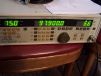
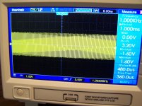
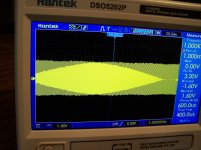
Here are the pictures of my scope screen.
Modulated 1khz signal from my generator at the audio out of the tuner.
I guess I was only seeing the 1 khz audio at the output of the tuner after all........Lol!
I thought I was actually seeing the RF carrier
Attachments
I was able to get most of the alignment settings completed on my spare practice unit but am still having an issue with alignment procedures # 20 and 21 on the attached alignment sheet.
I used my Amber distortion meter for all other distortion readings and had no problem seeing the changes on the analog meter as I was adjusting the pots......as a matter of fact, most of the factory settings were dead on or very slightly off. But with procedure 20 and 21, I was not able to see any changes happen at all when adjusting the pots. Those procedures require me to feed a 10 khz into my generator which I did from the Amber and read for distortion but could not see any changes no matter what configurations I tried.
I did make sure I had the generator set for external input and was clearly able to to see the 10 khz signal at the audio output of my tuner on my scope. The generator selector was also set for MAIN and L as per the procedure.
I do have another generator that I had tried using to feed the generator with but had the same results. At first I thought perhaps the other generator output signal might have to high a distortion level which was not allowing me to see any changes when adjusting the pots but like I said, even the Amber generator is giving me the same results so I'm confused.
Update!..........
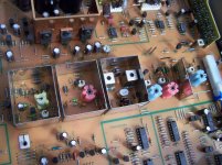
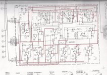
I looked over the attached schematic for the distortion cancelling circuit board where all of the distortion alignment pots are located.
Alignment # 20 and 21 pots are located on the lower left hand corner and each adjust the input of both halves of IC 15 .
So this is what I tried......I turned off the power and connected a test lead to pin 7 of the chip and connected to the distortion meter and tried once again to adjust VR 9 and was able too see great changes to the analog meter of the distortion meter. I set the pot for the lowest distortion level and it brought me to almost identical factory setting so I'm guessing I must be on to something.
I then did the same thing for pin 1 and VR 8 and I had the same results!
So my question is.......am I actually reading distortion and is it ok to do it like this?
And why the heck couldn't I get the same results at the audio output just like the rest of the distortion readings from that circuit board without having to go right to the chip pin out?
I used my Amber distortion meter for all other distortion readings and had no problem seeing the changes on the analog meter as I was adjusting the pots......as a matter of fact, most of the factory settings were dead on or very slightly off. But with procedure 20 and 21, I was not able to see any changes happen at all when adjusting the pots. Those procedures require me to feed a 10 khz into my generator which I did from the Amber and read for distortion but could not see any changes no matter what configurations I tried.
I did make sure I had the generator set for external input and was clearly able to to see the 10 khz signal at the audio output of my tuner on my scope. The generator selector was also set for MAIN and L as per the procedure.
I do have another generator that I had tried using to feed the generator with but had the same results. At first I thought perhaps the other generator output signal might have to high a distortion level which was not allowing me to see any changes when adjusting the pots but like I said, even the Amber generator is giving me the same results so I'm confused.
Update!..........
I looked over the attached schematic for the distortion cancelling circuit board where all of the distortion alignment pots are located.
Alignment # 20 and 21 pots are located on the lower left hand corner and each adjust the input of both halves of IC 15 .
So this is what I tried......I turned off the power and connected a test lead to pin 7 of the chip and connected to the distortion meter and tried once again to adjust VR 9 and was able too see great changes to the analog meter of the distortion meter. I set the pot for the lowest distortion level and it brought me to almost identical factory setting so I'm guessing I must be on to something.
I then did the same thing for pin 1 and VR 8 and I had the same results!
So my question is.......am I actually reading distortion and is it ok to do it like this?
And why the heck couldn't I get the same results at the audio output just like the rest of the distortion readings from that circuit board without having to go right to the chip pin out?
Attachments
Last edited:
...overall the factory settings were pretty much dead on.
I expected that. There is very little reason they would drift. Particularly the RF tanks: they do not "pick out a station" but rather "reject stuff far off channel". Functionally a waste of time (though kept you busy and off the streets for a few nights). If reception were bad, it wouldn't be drifted RF tanks but some failure. If parts were replaced, alignment check would be wise, but my impression is that transistor tuners are not so tight-tuned as the days when we replaced tubes willy-nilly. And within reason, the RF tank alignment mainly matters for WEAK signals. We usually favor strong signals, and a few-dB error in the RF hardly matters. If you lived here, we only have weak signals; I would align for best reception (highest signal strength) of WKIT, and maybe one of the two other listenable signals.
- Status
- Not open for further replies.
- Home
- Source & Line
- Analogue Source
- Kenwood KT-3300d Alignment Question