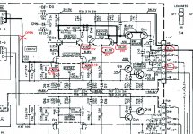
Hi everyone. I do not quite understand what happens with this equipment. I am working on one channel, the other does not work and has missing parts. I do not have enough current at the base of Q1 and Q3 dirvers. By disconnecting the D1 (STV 4H), it barely exceeds the bias current suggested by the service manual. I am using a variac and lamp in series to perform this test. As it was not destructive, connect the amplifier directly to the power outlet, but without any positive results. What I did find is voltages different from those indicated in the manual, in the collectors of Q3, there are 21V instead of 12.1, therefore, in the emitters of Q5 there are 21.4V. Try to exchange Q1, Q3 and Q5 with those of the other channel, but the fault persists, the rest of the voltages are correct. Currently, disconnect the bases of Q5 and the voltages in the collectors of Q3, they remain in 21V Any suggestions?
Attachments
Last edited:
You might have a shorted D5 or at least one bad solder joint. Do check -4.6 V and +28.9 along with other supply test points, and make sure input ground is where it's supposed to be.
Make sure to reconnect D1 before testing.
If you don't get enough current through D1, you need to check the Q11/Q13 leg, Q7/Q11 balance (drop over R74/75), check for any bad solder joints on any parts involved etc.
Can you test voltages at R9/R7 and R15/R17, just to make sure it's not the overcurrent protection being triggered?
You might have a shorted D5 or at least one bad solder joint. Do check -4.6 V and +28.9 along with other supply test points, and make sure input ground is where it's supposed to be.
Make sure to reconnect D1 before testing.
If you don't get enough current through D1, you need to check the Q11/Q13 leg, Q7/Q11 balance (drop over R74/75), check for any bad solder joints on any parts involved etc.
Can you test voltages at R9/R7 and R15/R17, just to make sure it's not the overcurrent protection being triggered?
When I started the repair, D7 was short. Currently, the tensions of -4.6 and +28.9 are present, also the input ground
Replace D1 with 4 x1N4007 in series, a maximum 2mV appears at the bias adjustment test points
I did not find bad welds, I will review this section Q7, 11, 9 and 13 and other suggestions, also the protection circuit.
I was doing tests with the bases of Q5 disconnected, but I have those voltages different from those marked in the circuit, does this seem normal to you ?, regardless of the rest of the circuit, who determines that in the collectors of Q3 should have 12V ?.
I will continue moving forward with these suggestions. Thank you sgrossklass
Latest tests
Remove Q6, Q8, Q10 and Q12.
Voltage drop on R75, 0.9V
Voltage drop on R74, 0.33V
Q8, Q10, Q12 and Q14, controlled with an analog ohmmeter in direct and inverse, OK.
Voltage drop in D10, 0.6V
VR6, offset adjustment, works well
Remove Q6, Q8, Q10 and Q12.
Voltage drop on R75, 0.9V
Voltage drop on R74, 0.33V
Q8, Q10, Q12 and Q14, controlled with an analog ohmmeter in direct and inverse, OK.
Voltage drop in D10, 0.6V
VR6, offset adjustment, works well
Hi.
New tests
current state, STV 4H diode connected, and everything previously disconnected, now connected, (except the protection circuit) idle current, 0mA (0 volts at test point), voltage between S- and S + 2.14V, the rest of the tensions, as I mentioned before.
Now, cut R19 of 47ohms, idle current appearance and it is possible to vary it by VR1 and adjust it to the value indicated in the manual, voltage between S- and S + 2.26V. But the voltages in base of Q5, continue in 21V instead of 12 as it is indicated in the diagram.
Any ideas? They ran out of me.
Thank you😕😕😕🙁🙁🙁
Have you checked the diode D5 in series with R19 for a short?
Are all the output transistors and drivers the originals? Are the 10 ohm base resistors OK?
Are all the output transistors and drivers the originals? Are the 10 ohm base resistors OK?
Have you checked the diode D5 in series with R19 for a short?
Are all the output transistors and drivers the originals? Are the 10 ohm base resistors OK?
D5 its OK, (0.6V drop), drivers, output and base resistors are originals and Ok.
All rather odd. Have you checked R53/54 as well as the offset pots for good contact and solder joints? The voltages you are mainly worried about all hinge on input stage current. Note that these FET input stages may well exhibit reduced current at startup and require some warmup.
Going by R74/75, your D9/Q13 current mirror does not seem to be doing very much, current balance is way out of whack. Make sure D9 is not shorted by any chance or there's a bad connection between Q13 and R75.
Going by R74/75, your D9/Q13 current mirror does not seem to be doing very much, current balance is way out of whack. Make sure D9 is not shorted by any chance or there's a bad connection between Q13 and R75.
Hi.
New Test.
Voltage drops on each component
R19, open R19 on D1 open
Idle: 21mV(test point) 0mV 35mV
VR75: 0.87V.............................0.069V.....................0.9V
VD9: 0.65V.............................0.64V......................0.5V
VR71: 0.79V.............................0.54V......................0.038V
VR73: 0.96V.............................0.586V....................0.13V
Vbe Q7+VR75:1.48V.................1.487V.....................1.46V
Vbe Q11+R75:1.49V.................1.491V.....................1.499V
VceQ13+VR73: 1.126V..............53.4V......................48V
VbeQ13+VR73: 1.456V.............1.187V.....................0.55V
VR1: 0.017V............................0.12V......................0.33V
VR3: 0.001V............................0.009V....................0.0023V
Vbe Q1: 0.573..........................0.643V...................0.67V
Vbe Q3: 0.53V.........................0.574V....................0.592V
VbeQ5: 0.572V........................0.43V......................0.57V
VbeQ6: 0.57V.........................0.42V.......................0.51V
VR7: 0.0033V..........................0.0V........................0.012V
VR8: 0.0024V..........................0.0V.......................0.0036V
It seems that the current that delivers Q11 does not return completely through Q13. 😕😕😕
😕😕😕
New Test.
Voltage drops on each component
R19, open R19 on D1 open
Idle: 21mV(test point) 0mV 35mV
VR75: 0.87V.............................0.069V.....................0.9V
VD9: 0.65V.............................0.64V......................0.5V
VR71: 0.79V.............................0.54V......................0.038V
VR73: 0.96V.............................0.586V....................0.13V
Vbe Q7+VR75:1.48V.................1.487V.....................1.46V
Vbe Q11+R75:1.49V.................1.491V.....................1.499V
VceQ13+VR73: 1.126V..............53.4V......................48V
VbeQ13+VR73: 1.456V.............1.187V.....................0.55V
VR1: 0.017V............................0.12V......................0.33V
VR3: 0.001V............................0.009V....................0.0023V
Vbe Q1: 0.573..........................0.643V...................0.67V
Vbe Q3: 0.53V.........................0.574V....................0.592V
VbeQ5: 0.572V........................0.43V......................0.57V
VbeQ6: 0.57V.........................0.42V.......................0.51V
VR7: 0.0033V..........................0.0V........................0.012V
VR8: 0.0024V..........................0.0V.......................0.0036V
It seems that the current that delivers Q11 does not return completely through Q13.
😕😕😕- Home
- Amplifiers
- Solid State
- Kenwood KA801 HELP!!!