Yes, 4.7k or 4700 ohms. Make sure by measurement you have the right value. Going to low accidently (lower than the 3.8k fitted) could cause damage. Going higher can only reduce the current in the output stage, not increase it. Its trial and error depending on the range of adjustment the preset provides.
I can't reliably answer your last question. In the UK they would have been designed and marked as 240 volts. We now have nominally 230 vac but in reality nothing changed with our distribution network, only the tolerances, and its quite common to see up to 245 volts (or even higher) at a wall socket.
I can't reliably answer your last question. In the UK they would have been designed and marked as 240 volts. We now have nominally 230 vac but in reality nothing changed with our distribution network, only the tolerances, and its quite common to see up to 245 volts (or even higher) at a wall socket.
They are replaced. They right channel sounds fine, the left one sounds scratchy. When I removed the speakers, I heard a silent noise of the music coming from the left side of the amp. A bit like at a turntable cartridge without speakers. After half a minute it burned R79 (330 Ohm). I checked the transistors, they seem fine. R79 has still 330 Ohm, it should be replaced, right?
That resistor should run cold under all conditions. It is normal to hear sound from a transistor amp with no speakers connected... the mechanisms why are a bit obscure... but yes, that is normal. It sounds like you perhaps had the volume pretty high to make it very noticeable though.
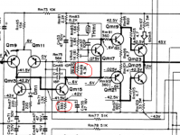
The resistor you have replaced (top one circled) can only reduce the output stage current. Did the current adjust correctly with a 4k7 or not ?
(It might be advisable to use a bulb tester if there is are any doubts)
The resistor you have replaced (top one circled) can only reduce the output stage current. Did the current adjust correctly with a 4k7 or not ?
(It might be advisable to use a bulb tester if there is are any doubts)
Attachments
strange, can you maybe try to explain why? Or what do I have to google?
silly me.. I forgot to cut the rest of the resistor after soldering. The result was that the resistor touched the cover..
Now the amp works again.
Yes I replaced them with 4.7k. Current is now 45mV at both channels, so still 25mV to high 🙁
silly me.. I forgot to cut the rest of the resistor after soldering. The result was that the resistor touched the cover..
Now the amp works again.
Yes I replaced them with 4.7k. Current is now 45mV at both channels, so still 25mV to high 🙁
OK 🙂 That sounds like a lucky escape for the amp 😱
So you need to go higher still in increments. 5K1 is the next preferred value but try a 5k6 if that is all you have. If you take the resistor out altogether then the current should fall to zero (the amp would still work but you would have crossover distortion)
The bulb tester is a mains filament bulb in series with the mains... it helps prevent damage to the amp in the event of a catastrophic short or failure.
(Just increase the value of the resistors a little and test again)
No... why do you think that ? Is it because we are having to alter things to get it correct ?
All we are trying to do is bring the voltage across QM17 down a little (and we are talking millivolts of change) so that the drivers conduct a little less and consequently also the output transistors.
I suspect one of the main reasons for having to do this is that the rails are a little on the high side and the amp isn't particularly stabilised in that regard.
well, I guess R89 and R90 were just fine in the original design? So why are they off now?
This amp was sold in Germany, so the designers must have known about the slightly higher voltage.
Is it just bad design or still within the margin?
This amp was sold in Germany, so the designers must have known about the slightly higher voltage.
Is it just bad design or still within the margin?
Last edited:
Well its not the worlds most DC stable of designs and if its marked 220 volts then that is the intended range. It is what is 🙂 a perfectly competent text book type of design.
I don't think anything will have changed value or failed, your just seeing the effect of the higher rails pushing up the current that flows through Qm17 and consequently that generates a slightly higher bias voltage that also happens to be out of the range of the adjustment of the design.
Without actually examining the amp, that's my best guess. And also as mentioned earlier, if any of the devices have been replaced with more modern semiconductors (which tend to have slightly different properties)
I see, thanks a lot for the patience and helpful explanations 🙂
Is there a way to improve the power supply? I already replaced the 6800uF with 10000uF caps. I read something about bypass caps, but I don't get it..
Is there a way to improve the power supply? I already replaced the 6800uF with 10000uF caps. I read something about bypass caps, but I don't get it..
from idntr Most of the caps are replaced and so far it's sound quite nice
If this also include ceramics and or other compensation capacitors any mistake there could make the amp oscillate and also draw more idle current than its supposed to be since even with no load (speakers) there is a zobel net work in the output that will act as a load only in high or very high frequency conditions ...
To make this more simple
measure bias over left ch, static conditions, no load ,no input ,volume down , then as you said bias is higher than is supposed to be, then remove from the circuit Rm 111 for left ch or Rm112 from right ch depending the ch you are working with ....
---If bias drops your fighting oscillation
---If bias remains the same you either have some error or any of your resistors have very high tolerance or other short of error
Kind regards
Sakis
Is there a way to improve the power supply? I already replaced the 6800uF with 10000uF caps. I read something about bypass caps, but I don't get it..
Modifications like that won't change anything that affects the DC stability. As for improving sound quality, my advice would be to stick with the original values.
Morning Sakis 🙂
we are probably getting better .... except pm messages ...and emails may be in the feature we may have a dedicated telephone line ...may serve things faster😀😀😀
- Status
- Not open for further replies.
- Home
- Amplifiers
- Solid State
- Kenwood KA-6100 BIAS to high