Yes, the diagram shows 8 pins. I thought that was what the original one had (although without looking at the circuit back then I assumed they were for loudness tappings)
If you post a picture of the new pot we should be able to tell you the way to connect it. The 15k fixed resistors connected to the original appear to be to fake a log law. They are not used as a frequency dependent loudness tapping.
If you post a picture of the new pot we should be able to tell you the way to connect it. The 15k fixed resistors connected to the original appear to be to fake a log law. They are not used as a frequency dependent loudness tapping.
Attachments
Yes, the diagram shows 8 pins. I thought that was what the original one had (although without looking at the circuit back then I assumed they were for loudness tappings)
Likewise - but it's very unusual to use a tapped linear pot rather than a log one 😀
As Mooly has already suggested, simply wire the pot ignoring the extra tap and 15K resistors (although connecting them won't make 'that' much difference, but no point in extra work to make it worse).
The 15k fixed resistors connected to the original appear to be to fake a log law.
The truth is that the Original Kenwood pot it does an remarkably good job about volume control stepping.
Checked in detail my own Kenwood pot and it is different.
If I ever have to replace it I would probably use one coming from a car stereo.
Likewise - but it's very unusual to use a tapped linear pot rather than a log one 😀
Hi,
Its well known but not seen that often. Channel matching
of the fake law pot is much better than a logarithmic pot,
especially at low volume levels / settings.
rgds, sreten.
Its well known but not seen that often. Channel matching
of the fake law pot is much better than a logarithmic pot,
especially at low volume levels / settings.
Presumably you've not read post #10 😀
Hi,
Thanks or the posts..
Here are the photos:
1)The first image shows the original pot on the board.
2)The second image shows the two pots in the same rotation as the original as fitted, with the location pin at the bottom.
3)The third image shows the board flipped over. Black pen mark shows the top edge of the board, as in the first image.
4) In the fourth image I have numbered the pins of both pots, is this correct ?
If not please could you give me the correct numbering
I should then just be able to wire the pins to the relative points on the board

Thanks or the posts..
Here are the photos:
An externally hosted image should be here but it was not working when we last tested it.
An externally hosted image should be here but it was not working when we last tested it.
An externally hosted image should be here but it was not working when we last tested it.
An externally hosted image should be here but it was not working when we last tested it.
1)The first image shows the original pot on the board.
2)The second image shows the two pots in the same rotation as the original as fitted, with the location pin at the bottom.
3)The third image shows the board flipped over. Black pen mark shows the top edge of the board, as in the first image.
4) In the fourth image I have numbered the pins of both pots, is this correct ?
If not please could you give me the correct numbering
I should then just be able to wire the pins to the relative points on the board
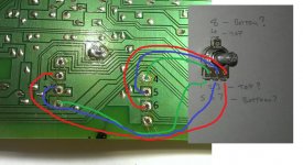
Trying to trace things from pictures is never easy but I think your in error with the numbers.
Listen... its easy 🙂 Lets hope my drawing is correct... check visually and with your meter. Forget the numbers I put on the PCB, this is easier.
Green wire... pot ground
Red wire...... pot input
Blue wire..... pot wiper
The two large areas on the PCB that the green wire go to should be ground in the amplifier. So if you measure from either of those to chassis ground there should be continuity. As long as that is correct then the red and blue are correct to. I think I can see they are linked anyway so that confirms it.
The tappings if you want to use them go to the unmarked pad on the board. You can use either gang of the dual pot to be either channel, it doesn't matter.
Attachments
Thanks Mooly ,
I've checked the continuity of the Green (ground) and it's ok.
Everything else seems to be correct and follow the correct tracks on the board to the relevant components as per your wiring diagram
The numbering I'd put on the pots was incorrect, I've updated it and things seem to make more sense.
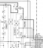
So if I understand correctly, to have the Log pot work the same as the original Linear pot I need to connect pins 8 & 4 and then replace R35 & R36 with Jumpers ?
I've checked the continuity of the Green (ground) and it's ok.
Everything else seems to be correct and follow the correct tracks on the board to the relevant components as per your wiring diagram
The numbering I'd put on the pots was incorrect, I've updated it and things seem to make more sense.
An externally hosted image should be here but it was not working when we last tested it.
So if I understand correctly, to have the Log pot work the same as the original Linear pot I need to connect pins 8 & 4 and then replace R35 & R36 with Jumpers ?
If your replacement is a log type then just leave the extra taps unconnected. If you connect them then the already log law will be altered to something else, not that effects the audio quality, just the amount of sound relative to the amount of rotation.
Does the amp have a loudness button ?
Nothing on that volume control as its shown on the circuit is anything other than just volume. Normally a frequency selective network would be connected to those taps on the pot for a true "loudness" facility but this hasn't. Its all resistive volume adjustment so no problems 🙂
Nothing on that volume control as its shown on the circuit is anything other than just volume. Normally a frequency selective network would be connected to those taps on the pot for a true "loudness" facility but this hasn't. Its all resistive volume adjustment so no problems 🙂
I just noticed that the KA-3020SE which the circuit diagram is for does not have the Loudness button. Mine is the KA-3020.... which does.

Actually now I've found a 100kB Pot, with 8 pins.
I guess that would be a better choice
100K ohm 8 Terminals Dual Linear Volume Control Taper Pot Potentiometer | eBay
I guess that would be a better choice
100K ohm 8 Terminals Dual Linear Volume Control Taper Pot Potentiometer | eBay
Leave the 15k's. Now we've discovered your model has the loudness function we just wire the new pot in to suit, which means using all 8 tabs and leaving the rest of the circuitry as original. That ebay one is cheap enough... wouldn't like to say what the quality would be like (will it last !)
- Status
- Not open for further replies.
- Home
- Amplifiers
- Solid State
- Kenwood KA-3020 Volume control