After receiving this this amp i noticed the previous owner must of decided a weight reduction was needed as random parts where pulled from the power amplifier board. After finally replacing (New caps and transistors) and rebuilding the amp it works! But when i try to make the adjustments i run into a problem. in the manual it specifies that on one transistor the base voltage must be .5V (500mV) and on the other transistor it specifies that 20mA must go into the collector of the other. These measurements where both without load, volume down, all switches off, tone canceled and measured from the 4 2sd255 transistors. I also replaced both trimpots with multi turn enclosed types.
I can get to the .5v but when i adjust the current the voltage goes up. so at the moment i have it at 20ma .6V (.600mV) would this be ok?
Any Help would be much appreciated
I can get to the .5v but when i adjust the current the voltage goes up. so at the moment i have it at 20ma .6V (.600mV) would this be ok?
Any Help would be much appreciated
We would have to see the relevant part of the manual to get the context but generally you are adjusting the bias to give a known current flow in the output transistors. That current can be inferred without having to break the circuit to insert an ammeter by looking at the voltage across the emitter resistors and calculating it from that result.
Post some shots of the procedure from the manual.
Post some shots of the procedure from the manual.
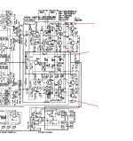
The 20ma that flows in the collector also flows in the emitter. The relationship between the three junction currents is Ie =Ib + Ic. Ib is low and can be disregarded in this case.
So all you need do is adjust for around 9.5 millivolts across either of the 0.47 ohm resistors. Follow any recommendations regarding warm up and don't be tempted to set the bias higher. It achieves nothing and could risk thermal runaway.
The 0.5 volts is just a typical DC voltage at that point. Its not to be used as an adjustment point or reference. Its the 20ma that matters.
(The bias will vary quite a bit with temperature, that's normal. Just aim for around the correct figure.)
Thankyou very much. Theres no specified wait time. Its only a schematic so i just let it sit for 10 minutes then adjust. Also i see in your tag you note the ltspice software. Im about to undertake third year electrical and am now branching into electronics and they mention that software. Have you had any experience with matlab also?
No, I've never used Matlab I'm afraid.
The important thing with bias adjustment is to make sure there is no possibility of thermal runaway. It might be worth checking and readjusting when the amp is really warm after playing for a while. If you make a note of the voltage across the 0.47 ohms then you can readjust easily without having to break the circuit to add the ammeter.
The important thing with bias adjustment is to make sure there is no possibility of thermal runaway. It might be worth checking and readjusting when the amp is really warm after playing for a while. If you make a note of the voltage across the 0.47 ohms then you can readjust easily without having to break the circuit to add the ammeter.
- Status
- This old topic is closed. If you want to reopen this topic, contact a moderator using the "Report Post" button.
- Home
- Amplifiers
- Solid State
- Kenwood ka-2600 adjustment