You connect the scope across the speaker terminals, and have the amp in the same condition as when you said "If I adjust Vr1, with the 4.7k setting it is either 0 or 1.5v, it seems to be either on or off"
When the jump from 0 to 1.5 volts occur, see if the any oscillation is present at the speaker output.
You need to select a resistor value that will allow the correct bias current in the output transistors to be set.
When the jump from 0 to 1.5 volts occur, see if the any oscillation is present at the speaker output.
You need to select a resistor value that will allow the correct bias current in the output transistors to be set.
thanks for your patience...🙂
so no input, just watch the scope to see what happens when the bias voltage goes from zero to 1.5v. I think I can set the scope to capture the image, so will try and do that and the post back here
again mooly, thanks - I usually use the scope, sig generator and distortion analyzer to check my work and make sure any changes to an amp results in a positive outcome(recaps/transistor subs/basic trouble shooting). If it is not driving you crazy, I appreciate your mentoring to figure out the next level of detail, as in problem solving what (certainly for me) is a tricky problem.
your humble student
thanks for your patience...🙂
No problem 🙂
We use the scope to see if the amplifier suddenly breaks into oscillation as you attempt to increase the bias current, and yes, no input signal for all these measurements. Any oscillation would be at very high frequency, perhaps in the 1 to 10 Mhz region and could be of any amplitude.
ok so now some weirdness.... I have both driver boards plugged into the backplane on the PSU board, but only one channel of the outputs connected, which is the channel I am adjusting with the scope across the outputs (speakers), I can get the bias to around 200mv with a 2.2k (really 2.5k) R13 value. So I turn off the amp make an adjustment on VR1 and turn back on I get 0v of bias- so something is amiss. I have a meter across Qe5 C and E, and the voltage moves smoothly as I adjust Vr1- with R13 at 2.2k, it maxes out at about 2.2 volts, the higher value for R13 the lower the voltage range. I will replace the main relay, and I need new trim pots for Vr1 (the ones I ordered "face" the wrong way, though the existing trim pots measure OK. It will take me a day or so to go though and check everything (again) and see if I can get a consistent behavior, which can then be diagnosed. That said the Self book has given me a better insight into what the circuit is doing, so hopefully it will be a matter of getting the right value for R13. thanks again, I will report back
Is the bias dropping to zero when you turn off and on because the amp has cooled slightly ? What happens if you leave it on for a few minutes ?
Once set, the voltage across Qe5 should be fairly similar under all conditions. So set the bias correctly, measure and record the voltage across Qe5 and then compare the result with the amp has been turned off and on. It shouldn't be massively different, just a few 10's of millivolts at most.
Everything seems to points to the circuit being somewhat critical on the devices used... and this is something I have encountered before on older equipment.
Hi so here is the scoop. turned on the amp from cold and got reading of about 250mv. Turn off and move Vr 1 towards minimum (about 9 oclock) and turn back on and get 30mv, so I leave on for about 15 mins with the following characteristics: T0 Qe5 C to E 2.33v bias 30mv T0+5min Qe5 2.31 bias 37mv T0+10min Qe5 2.30 bias 40mv T0+15 min Qe5 2.28 bias 42mv -and looking stable Oscilloscope OK ( a low frequency fluctuation but at 500mv resolution so probably because the amp and power supply boards are hanging out of the back of the amp) R13 1.5k (really 1.8k) then I turn it off and back on We5 is about 2.8v bias around 285mv and climbs over 300mv lots of noise on the scope about 2-4v of solid noise (1ms resolution) I do this a bunch of times, once it is 40mv all the other times it is approx 300mv. I left it for a while to cool down (the heatsinks were not warm) and the same 300mv result. could it be the thermistors? Thanks again mooly (btw delay in getting it done was to refurb a NAD2200-which worked out well and sounds very good indeed)- oh and I do this for fun..🙂
Lets just clarify a couple of things here.
The bias current is always (99% of amps) measured and set by looking at the voltage across one of the emitter resistors in the output stage, and typically these are in the 0.2 to 0.5 ohms range. This means the voltage across these resistors could be as high as 50 millivolts (no more and typically much less) and should be either quoted (or able to be derived) from information in the service manual.
DC offset (this is the DC voltage at the speaker terminals) should always be essentially zero (or a worst case maximum of -/+ 100mv) and should not vary as bias current is altered.
This 'noise' you are seeing almost certainly points to instability and oscillation. The scope trace should be a single clean line at all times with any 'noise' limited to random thermal noise (hiss) and that would not be easily visible on most scopes, even if they are on their most sensitive setting of just a millivolt per division.
So it all sounds as though this transistor swap has caused major problems with the stability of the amp being affected. Increasing Ce8 (1pf) to something like 4.7 or 10 pf and/or perhaps increasing Ce8 to something like 47pf might give some clues (stop the noise) but its risky without getting an overall feel for what is going on.
Hi Mooly, yes bias and DC offset definitions agreed- and consistent. There was a service note (attached) which Kenwood put out apparently to solve an oscillation problem. I have undertaken these modifications, which worked well for the original transistor set. I think upping Ce8 (now 3pf) to around 10pf is a good initial start point, though I would like to figure out the roll off this additional capacitance will apply. Thanks again
Attachments
Hi Mooly, yes bias and DC offset definitions agreed- and consistent.
There was a service note (attached) which Kenwood put out apparently to solve an oscillation problem. I have undertaken these modifications, which worked well for the original transistor set.
I think upping Ce8 (now 3pf) to around 10pf is a good initial start point, though I would like to figure out the roll off this additional capacitance will apply.
Thanks again
That all reads as if the stability is very marginal and totally dependent on the exact semiconductors being used. This is something that crops up a lot with older Japanese gear unfortunately.
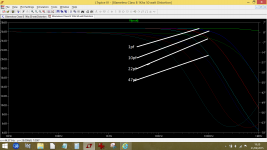
This shows an amp with the same feedback components values as yours and the response with 1, 10, 22 and 47pf caps across the 56k feedback resistor. This is a wide bandwidth amp, yours may or may not have the extended response of this one in which case the effects will all tend to be much less as the bandwidth is limited by other aspects of the design.
This shows an amp with the same feedback components values as yours and the response with 1, 10, 22 and 47pf caps across the 56k feedback resistor. This is a wide bandwidth amp, yours may or may not have the extended response of this one in which case the effects will all tend to be much less as the bandwidth is limited by other aspects of the design.
Attachments
Awesome..thank you
does this imply that if I put the circuit (or the driver and output part at least) into LT spice I can simulate the conditions?- and LT spice is something I am learning-
on a pragmatic note I think I will try a couple of different cap values and see what occurs. I think I will also substitute the output transistors and see if that makes a difference.
To date when working on older japanese amps I have had no similar problems, but this design appears to have some constraints.
So looking at the data sheets the main difference on the transistors, aside from ability to handle larger voltage/current and given the instability:
2SD281/2SB536:
Ft 40Mhz Cob 35pf Hfe about 100
MJE15032/33:
Ft 30mhz Cob not stated Hfe about 60
2SA673A/2Sc1213A
Ft 120mhz (673A) Cob 7pf (673) Hfe about 250
KSA1013/KSC2383
Ft50 (1013) 100 (2383)Cob 35/20pf (673/2383) Hfe about 250
2SC1416
Ft not known Cob 6pf Hfe about 350 Vcb 6v Ie 2ma
KSC1845
Ft 100mhz Cob 2.5pf Hfe about 400
2SA620
Ft 60mhz Cob 3pf Hfe 250
KSA992
Ft 100mhz Cob 3pf Hfe about 400
2SC1451:
Ft 65mhz Cob 4pf Hfe 150
KSC3503:
Ft 150Mhz Cob 2.6 Hfe about 200
So I will try closer substitutes for 2SC1451 (Ft), and ksa1013/ksc2383 (higher cap), though as they are the current limiters, I am guessing that wont make a huge impact.
the general opinion is that KSC1845 is a good sub for 2sc1416. The 2SA620/KSA992 should be OK.
Based on the assumption (perhaps incorrect) that the higher speed (Ft) and Capacitance variance may be tipping a somewhat cantankerous circuit over the edge.
thanks again I will report back
Yes, trying it in LTspice could be instructive as a means of exploring the stability margins. The current limiters have zero effect until they are triggered.
Does this amp use a zobel network on the output ?
Does this amp use a zobel network on the output ?
Miller capacitor C9 looks like it is too small to do any real good. Especially if you've changed drivers and/or outputs for something that has a different Cob or Cbe.
Making this cap small is a trick to get high slew rates, but that comes at the cost of having to keep a close eye on all the non-dominant poles. Without really good models, good luck in nailing those down. The whole reason for making the Miller pole dominant (that is, low in frequency) is to reduce this sensitivity.
Making this cap small is a trick to get high slew rates, but that comes at the cost of having to keep a close eye on all the non-dominant poles. Without really good models, good luck in nailing those down. The whole reason for making the Miller pole dominant (that is, low in frequency) is to reduce this sensitivity.
I have attached the overall circuit and the pages of the service guide that describe the amp section.
I am not sure if it has a Zobel network.
I will translate the circuit for the amp section into LT spice (which given my very limited LT expertise will take me a while...)
thanks again
I am not sure if it has a Zobel network.
I will translate the circuit for the amp section into LT spice (which given my very limited LT expertise will take me a while...)
thanks again
Attachments
success
Hi Mooly
I am (very) happy to report that using 4pf for C8 and new 1.8k (1%) resistors for R13, I have been able to get the beast to bias at 30mv....🙂
The circuit does seem rather "sensitive", and after some experimenting, this combination seems stable. I will reassemble and leave it on soak for a while and make sure everything is as it should be.
Thanks so much for helping me understand and diagnose this. I will put the circuit into LT and try and further understand why the circuit is so sensitive. Perhaps the miller cap is too low, but one I have figured out how LT works, I will try some simulations to see if I can understand the principles at work.
Now I just have to figure out why the Stereo light comes on just off the center dial position in the FM section (no I have never done an FM alignment before, and yes I should get an old crappy tuner to play with first)....but how hard can it be and what could possibly go wrong...
Thanks again for all your input
Excellent stuff  It does indeed sound to be very sensitive regarding its stability margins. Simulating it would certainly let you see the effect of altering the caps though, even if the basic instability didn't show. Worth doing I would say.
Full alignment is very very hard. You need all the right equipment. Ferrite dust cores have a habit of cracking as soon as they are moved.... but the good news is that the alignment should be fine. The one adjustment that often gives trouble is the FM stereo 38kHz oscillator and typically this is a pre-set pot. Just turn it to and fro a few times to clean it up and then set it to the middle of the two extremes where the stereo light illuminates. Use a weak signal for adjustment. Don't touch anything else and don't physically move any components in the RF stages because that will alter the stray capacitance between parts and that can alter alignment.
It does indeed sound to be very sensitive regarding its stability margins. Simulating it would certainly let you see the effect of altering the caps though, even if the basic instability didn't show. Worth doing I would say.Now I just have to figure out why the Stereo light comes on just off the center dial position in the FM section (no I have never done an FM alignment before, and yes I should get an old crappy tuner to play with first)....but how hard can it be and what could possibly go wrong...
Thanks again for all your input
Full alignment is very very hard. You need all the right equipment. Ferrite dust cores have a habit of cracking as soon as they are moved.... but the good news is that the alignment should be fine. The one adjustment that often gives trouble is the FM stereo 38kHz oscillator and typically this is a pre-set pot. Just turn it to and fro a few times to clean it up and then set it to the middle of the two extremes where the stereo light illuminates. Use a weak signal for adjustment. Don't touch anything else and don't physically move any components in the RF stages because that will alter the stray capacitance between parts and that can alter alignment.
excellent advice- I have a Sencore SG80 and a HP334 with a RF capable meter, plus scope, freq counter etc- I will check the 38Khz oscillator and report back on this
and yes I will take the time to capture the circuit in LT as I am still intrigued as to why it is so sensitive
thanka again
and yes I will take the time to capture the circuit in LT as I am still intrigued as to why it is so sensitive
thanka again
- Status
- Not open for further replies.
- Home
- Amplifiers
- Solid State
- Kenwood 9400 bias problem