Hi
I am rebuilding a Kenwood 9400 and as I have replaced most everything (including the tome control IC's/power supply caps/transistors and small diode bridges/main power supply caps/all the other electro's/volume control/lamps and more...sigh) I had the bright idea to change the transistors on the main amp driver boards.
So prior to revamping the amp boards everything "worked", audio out of both channels etc. However occasionally the relay would not click on, so I thought it could be the boards and to make a better job of it, I decided to change all the transistors (I had already done all the electro's).
Now when I try and bias the power amps there is close to 1.5V across the power transistor emitters- and they dont like that!
I have pulled each power transistor (2SD287/2SB539) and they all test good with my trusty Peak transistor tester. No matter where VRe1 on the amp driver boards is set (mid/high/low) the voltage does not change for the few seconds I leave it on.
Here is the list of the substitutions I have made:
Qe1 and Qe2 was 2SA620 now matched (HFE) KSA992FBU
Qe3 was 2SC1451 now KSC3503
Qe4 and Qe10 was 2SD381 now MJE15032
Qe5 was 2SC1416 now KSC1845
Qe6 and Qe9 was 2SA673 now KSA1013
Qe7 and Qe8 were 2SC1213 now KSC2383
Qe11 was 2SB536 now MJE15033
I have undertaken the mods on the PCB as per the service note and did this prior to replacing the transistors. As both channels exhibit the same behavior, I have concluded that I have caused the problem.
I did measure the output of the boards (pins 8/9 and 13/14) that feed the bases of the power transistors and they are both about 0.5v.
The following measurements were made for the transistors:
Qe1 & Qe2- both collectors at/near B- (56v for Qe1 and 58v for Qe2), both emitters are 0v and the base of Qe2 is 0.6v
Qe3 base is -56v, emitter is -58v and collector is -37v (which is my current suspect)
Qe4 base is -58v, emitter is -57v and collector is 1.2v
All the power supply voltages are correct (14v rails are 13.75) and 55 volt rails are 58v, and the protection relay clicks, so the protection circuit seems to think all is good.
I am wondering about the thermistors and De1 at present, however any thoughts and insights would be greatly appreciated, as I am starting to wonder if it is the output transistors themselves?
I have attached a circuit of the driver boards
Thanks
Attachments
You dun goofed. Either put back the original transistors or spend the rest of eternity faultfinding this thing. It doesn't sound like you're an expert in the area, something that's certainly required to get this thing going again, I'm afraid.
Modern manufacturing and doping techniques mean that new transistors can sometimes have (significant) differences in basic characteristics such as vbe/Ic. You may find a tweak to the vbe multiplier corrects the problem.
Your voltages sound OK given that you are measuring from ground... you should find if you measure across the junctions then you get a far more reliable result. For example your QE3 readings of E and B suggest 2 volts across the junction which isn't possible for a good device, yet the more important voltages on the output bases are fine.
For an initial test remove R13 (1k8) and the current should fall to zero in the outputs. If it does then try increasing R13 to 2k2 or 2k7 and see if it adjusts OK.
Thanks Mooly, I will try the resistor and report back, also will post the voltages across the transistors.
This is one of the many reasons that I participate here, which is to say to learn.
many thanks
This is one of the many reasons that I participate here, which is to say to learn.
many thanks
You should find ALL the transistors have the magic 0.65 volts or so (give or take) across the base/emitter junctions. The NPN's will have the base positive with respect to the emitter, vice versa for the PNP's.
Old transistor types often have "the wrong pinout" comapred to what you're used to. Don't discount the possiblity that one or more is in wrong. Checking the vbe's is a good start - but also remember that E-C breakdown volatges can be low, and so can reverse betas. Even Shelock Holmes ruled out the impossble first.
Hi
yes I thought I was very careful checking the pin outs, however I am quite capable of errors, though I did go back and check them again to be sure.
So as Mooly suggested I checked the voltage across base/emitter, and all good (0.6v or near) for Q3,Q4,Q10,Q11,Q5...but Q7 and 9 and Q6 and 8 are all showing above 2 volts(positive or negative as appropriate).
I had disconnected all the output transistors when I did these tests
When I measured these yesterday with reference to ground I had the following results:
Qe6 emitter 1.1/base 0.1/collector 0.1
Qe8 emitter 0.6/base 1.2/collector 0.0
Qe7 emitter 1.0/base 0.65/collector 0.0
Qe9 emitter 0.1/base 0.5/collector 0.65
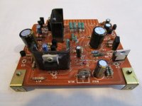
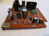
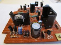
I have attached a couple of photos of one of the boards.
And of course in hindsight, I should have done one channel at a time...doh!
so much for being an experiential learner
yes I thought I was very careful checking the pin outs, however I am quite capable of errors, though I did go back and check them again to be sure.
So as Mooly suggested I checked the voltage across base/emitter, and all good (0.6v or near) for Q3,Q4,Q10,Q11,Q5...but Q7 and 9 and Q6 and 8 are all showing above 2 volts(positive or negative as appropriate).
I had disconnected all the output transistors when I did these tests
When I measured these yesterday with reference to ground I had the following results:
Qe6 emitter 1.1/base 0.1/collector 0.1
Qe8 emitter 0.6/base 1.2/collector 0.0
Qe7 emitter 1.0/base 0.65/collector 0.0
Qe9 emitter 0.1/base 0.5/collector 0.65
I have attached a couple of photos of one of the boards.
And of course in hindsight, I should have done one channel at a time...doh!
so much for being an experiential learner
Attachments
a few more measurements:
Qe11 emitter -0.5v/base -1.0/collector -60v (B-)
Qe10 emitter 0.5/emitter 1.0/collector 60v (B+)
all referenced to ground
Qe11 emitter -0.5v/base -1.0/collector -60v (B-)
Qe10 emitter 0.5/emitter 1.0/collector 60v (B+)
all referenced to ground
Qe6 emitter 1.1/base 0.1/collector 0.1
Qe8 emitter 0.6/base 1.2/collector 0.0
Qe7 emitter 1.0/base 0.65/collector 0.0
Qe9 emitter 0.1/base 0.5/collector 0.65
These four transistors are used for over current protection... and I think we can explain your measured results 🙂
You will see the base and collector of each pair are linked but that they don't connect to anything else. That means that this point is 'floating' and so subject to erroneous readings... yes, they still obey the laws of transistor operation but what you are probably doing is introducing stray AC noise when measuring, and because that node is 'floating' the reading is all over the place.
The important thing I see is that the common point of all four transistors, which is the amplifier output line, is at essentially zero volts, which is correct.
Everything up to now points to a simple issue with the vbe multiplier not being able to reduce the bias. Removing R13 as a quick check should force the current to zero.
thanks mooly, i appreciate the explanation.
I will remove R13, connect the outputs and let you know the results.
The AC noise may have been introduced by the Tektronix DMM's I was using.
I will remove R13, connect the outputs and let you know the results.
The AC noise may have been introduced by the Tektronix DMM's I was using.
Hi Mooly
yes removing R13 results in 0v across the emitters of the outputs.
so with the original value of R13 being 1.8k plus the maximum resistance of Vr1 being 1k, gives a total of 2.8k, which was resulting in a bias voltage of (around) 1.5v.
Does this mean that, as V=I X R which equates to 1500 (mv)= I x 2800,
so I=(roughly) 0.5A? or is it 1.5= I x 2800 so I= 0.0005A?
guess who has not done this for a very very long time...🙂
Not exactly 🙂 You can't get at the final current in the output stage from those values.
Qe5 and its resistors enables the voltage across Qe5 to be varied as the preset is turned. The exact voltage you get across the transistor actually depends on the individual transistor to quite a large extent, its gain and just its basic characteristics determine that.
To get current flowing in the output transistors requires you to develop enough voltage across Qe5 to overcome the four base/emitter junctions of the drivers and outputs. If we say around 0.65 for each then you need at least 0.65 * 4 = 2.6 volts to be available across Qe5.
The circuit as originally designed suits the original transistors very closely, there is no room for extra adjustment without you changing the value of that 1.8k. Its a trade off between fine adjustment and it being difficult to damage the amp by mis adjustment, or making the range so large that it goes from zero to destruction in a quarter turn.
So you need to now fit higher values for R13 so that it adjusts correctly. If you go to high then it just wont adjust at all and it will be stuck on zero.
Mooly, thanks yet again!
so two thoughts:
1 replace R13 with 2.2k/2.7k as per your suggestion so as to get VR1 into a range where bias can be adjusted (should I put in a 1/2w rather than 1/4w resistor?)- and given your comment, start high first?
2 Consider replacing all the outputs with MJE21193/MJE21194 which I suspect may better suit the more modern components I have installed on the driver boards. -this may also require R13 to be adjusted.
I will undertake 1 above and report back.
and a further (quite possibly dumb) question,
"across Qe5" what does that mean?
thanks again, I am trying to understand the "how" as well as get the amp working, and I greatly appreciate your patience and tutoring
I replaced R13 with a 2.7k resistor, and still got about 1.4v....
should I try a much higher value (10k)?
should I try a much higher value (10k)?
Yes, you'll have to go as high as needed, but do it incrementally, try 3k3 and then 3k9. 10k is probably a bit much but you could work down from there.
You will need to monitor the current once set and make sure that it is stable and that there is no tendency to thermal runaway as the amp warms. Play it loud and recheck the current hasn't gone to high.
You will need to monitor the current once set and make sure that it is stable and that there is no tendency to thermal runaway as the amp warms. Play it loud and recheck the current hasn't gone to high.
Hi
I have a resistor substitution box which I have installed, and found that the 4.7k setting (really 4.9k), gives 0v, where as 3.3k (really 3.5k) gives 1.5v.
If I adjust Vr1, with the 4.7k setting it is either 0 or 1.5v, it seems to be either on or off.
I will test the thermal resistors mounted on the heat sinks, as they are part of the Qe5 circuit, however as Vr1 is between Qe5 base and emitter I have rechecked the specs of the original 2SC1416 and the replacement KSC1845, and aside form the 1845 handling higher voltages, they are the same (and Hfe is about 400 for both).
So the question would seem to be why is Qe5 acting as a switch?
I am waiting for new trim pots to replace the originals in case they are part of the problem, and will replace the original relay as well
Thanks again mooly- this has me quite confused
So the question would seem to be why is Qe5 acting as a switch?
Measure the voltage across Qe5 C and E as you vary the preset. It should alter smoothly.
It is (very) possible that you might have some form of instability (oscillation) which would be down to the different characteristics of the transistors. That needs a scope to confirm whether or not that is happening.
Thanks will do
I do have a decent scope.
I am also reviewing Self's book (Audio power amp design) to get a better understanding on VAS stages.
I do have a decent scope.
I am also reviewing Self's book (Audio power amp design) to get a better understanding on VAS stages.
Excellent. Scope the output and see if anything shows up when you see the current suddenly jump.
Have a read on what Doug says about vbe multipliers too.
Have a read on what Doug says about vbe multipliers too.
with the outputs disconnected, and R13 at 4.7k the voltage across Qe5 C and E ranges from approx 1.4 volts to 1.55 volts, smoothly when Vr1 is turned from min to max.
with R13 at 6.8k the range was 1.2v to 1.3v approx
with R13 at 10k the range was 1.1v to 1.2v approx
Thanks ,I am not sure what is meant by "scoping the output"
with R13 at 6.8k the range was 1.2v to 1.3v approx
with R13 at 10k the range was 1.1v to 1.2v approx
Thanks ,I am not sure what is meant by "scoping the output"
- Status
- Not open for further replies.
- Home
- Amplifiers
- Solid State
- Kenwood 9400 bias problem