Hi, not my first project but my first post.
Kelly KT3 90's vintage (manufacturer Musical Fidelity) high sensitivity floor standers. Twin bass/mid drivers in parallel, one in the top chamber rear ported and one in the lower chamber front ported.
Drivers 2 x Audax HM170Z12 1x Vifa 96db sensitive tweeter (Scanspeak & Peerless make an current equivalent)
I have looked at the crossover. Schematic here:
Interestingly it is the same board layout as Kelly KT2. But there are resistor differences between the two and the Kelly KT2 Audax drivers are HM170ZO
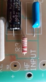
Q: The resistor R3 is Red Red Gold which I think is 2.2r so the circuit is 1 ceramic 2.2r @ R2 followed by same value different resistor type. (KT2 have a 0.22 ceramic there so reason I am confirming value)
Definitely upgrading the ceramics with Jantzen,Ohmite,Mills some such like but is R3 worth changing? Is it likely a carbon or film?
The LF cap C1 in the image has a rating of 20mF. Pretty sure it means manufacturer didn't have a mu sign and it is not micro Farad. Can anyone confirm my thinking?
Many thanks in advance
Kelly KT3 90's vintage (manufacturer Musical Fidelity) high sensitivity floor standers. Twin bass/mid drivers in parallel, one in the top chamber rear ported and one in the lower chamber front ported.
Drivers 2 x Audax HM170Z12 1x Vifa 96db sensitive tweeter (Scanspeak & Peerless make an current equivalent)
I have looked at the crossover. Schematic here:
An externally hosted image should be here but it was not working when we last tested it.
Interestingly it is the same board layout as Kelly KT2. But there are resistor differences between the two and the Kelly KT2 Audax drivers are HM170ZO
Q: The resistor R3 is Red Red Gold which I think is 2.2r so the circuit is 1 ceramic 2.2r @ R2 followed by same value different resistor type. (KT2 have a 0.22 ceramic there so reason I am confirming value)
Definitely upgrading the ceramics with Jantzen,Ohmite,Mills some such like but is R3 worth changing? Is it likely a carbon or film?
The LF cap C1 in the image has a rating of 20mF. Pretty sure it means manufacturer didn't have a mu sign and it is not micro Farad. Can anyone confirm my thinking?
Many thanks in advance
Attachments
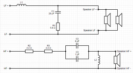
20uF and (6uF plus 1uf) look very typical for this sort of circuit.
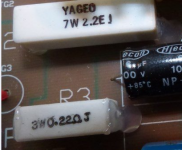
That 0.22R is a very small value but is a 3W ceramic type. There is a restoration thread at Art of Sound for the similar Kelly KT2:
Kelly Tranducers KT2
General upgrade to crossover, and a metal film 6.8uF tweeter capacitor. But looks the same circuit. Where a 1-2W metal oxide resistor is added to a tweeter filter it often is designed to act as a fuse in case of overdrive.
You often add a little 1R resistor when changing electrolytics to film types. Compensates for the ESR resistance. A £5 multimeter is always useful in these situations just to check things.
Don't expect much improvement though. It's a competent crossover already. Looks like aircoil on bass which is good.
Answered my own question it was the light. The photo in the box looked Red Red Gold Brown. On removal R3 was Red Red Silver Gold! So 5% 0.22ohm, matching the Kelly KT2 values.
I think I may see a difference. The ceramics were within tolerance:
R1 = 5.5 so 2% off
R2 = 2.1 so 5% off
R3 = 0.2 so 5% off
Replacing with Mills @1%
The electrolytics were way out!
C1 = 27.5uF! (value 20) and will be replaced with JB capacitors JFX polyprop
C2+C3 measured in at 8uF. Values 7uF. Replacing with 1x Jantzen Crosscap @ 4.3uF and 1x Audyn ZN SP @2.7uF (they just fit the board).
On your advice I will go check the ESR values to see if the R needs tweaking before I buy. But as all the resistors were under it will be win even if I go back to spec.