I went ahead and made a Bi-wire PCB for my original Kef104/2s I thought you all might be interested to see the design I came up with.


Be aware than there were small changes in the bi wires latest 104/2, so the coils values are certainly not the same than the monowirerd...while yours is a late version according the 1989 year number.
I rememberer wondering why in the mono pcb they use this very thin wire jumper on the main pcb plug to power the two bass units...as if they want to reduce for some reason the serie size of the wire gauge ?
Probably the main advantage of a bi wirered new pcb is to pull out the bass pcb for using large mkp cap, so making room for a new mid treble pcb inside with large area for the 250, 30, 50, 2 x 100 uf, etc caps to make it mkp for the LL and mylar for the conventional caps. The good and precise values of the new caps are more the trick than any else tweak to make it sound good. Of course pulling out the whole filter make you the life easier to try and error for the caps values the kef official shematic just give with small precision (while at kef they lost the folder where each cap value were noted with the serie number of the sold speaker for revisions and driver part swap if broken)
Last edited:
Thanks for the feedback and the good comments:Be aware than there were small changes in the bi wires latest 104/2, so the coils values are certainly not the same than the monowirerd...while yours is a late version according the 1989 year number.
I remember wondering why in the mono pcb they use this very thin wire jumper on the main pcb plug to power the two bass units...as if they want to reduce for some reason the series size of the wire gauge ?
Probably the main advantage of a bi wired new pcb is to pull out the bass pcb for using large mkp cap, so making room for a new mid treble pcb inside with large area for the 250, 30, 50, 2 x 100 uf, etc caps to make it mkp for the LL and mylar for the conventional caps. The good and precise values of the new caps are more the trick than any else tweak to make it sound good. Of course pulling out the whole filter make you the life easier to try and error for the caps values the kef official schematic just give with small precision (while at kef they lost the folder where each cap value were noted with the series number of the sold speaker for revisions and driver part swap if broken)
Regarding the crossover schematic, I did see that some schematics that showed that the later bi-wired design was more sophisticated again than the design used in my speakers. The all-pass filter for the mid speakers is a nicer design but I did not find any definitive values for the inductors so I did not dare to try to use that. Instead I used exactly the same schematic and just broke the link between the bass part and the mid-treble part. The inductors were removed from the older PCB an remounted. I did hear some folk tales that the inductors were individually wound to match the tolerance of the capacitors but the engineering time needed for this would have made the speakers even more expensive so I find this hard to believe. I spent some time when I was a student engineer winding coils in a factory - this is not something you want to mess with🤔.
Regarding the link for the Bass speakers, I saw this too. I Imagined that it was to isolate the drivers for production test purposes. It was a tiny wire, but the base inductor is already 300mΩ so they probably figured an extra 50mΩ would not hurt. However when I bought my speakers I was offered a "demo" of some expensive speaker wire which was an extra $100 (a lot of money then!) and I could hear the difference. As an Engineer I figured it was just that the better connected the drivers are to the Amp the higher the damping factor is and the more controlled the overshoot (2nd harmonic) becomes. With a 4 ohm system 1Ω of wire impedance is large. For this reason I designed out the link and used 10mm wide tracks on both sides of my PCB, plus 6mm wire (some of the same expensive speaker wire I had spare!) to the speaker terminals. I also replaced the 1mm internal cabling to with 2.5mm cable and used fatter spade connectors. I verified with an ESR meter that I lowered the internal impedance by ~150mΩ in total.
Regarding the capacitors, I had already ordered the Kit from Falcon Acoustics so I designed the PCB around those capacitors. The ESR of these capacitors is already low, I was measuring ~100mΩ for the 100uF caps (50mΩ for the 2 in parallel). Since the crossover was designed for NP Electrolytics I did not want to go to the more expensive capacitor types. Going double sided on the PCB allowed me to shrink the design by about 10% overall while maintaining the same fixing points.
For me the bi-wired design has 2 possible advantages:
- The PCB currents are separated so voltage drops do not interfere between the low and the mid-treble
- I can connect the bass side to the sub-woofer output of my amp giving the room equalizer one more degree of freedom.
I can not agree more from my souvenir at recaping them.
Seems from the shematic the 2% caps precision is about the ones that are not marked 10% on the shematic. The coils may have been ordered with specific demand to the manufacterer...
Of course there was perhaps a little marketing...the 0.5 % matching is between Right and Left speaker. You know you succeed the recapingcif the bass to mid sounds tight. ( there the precision of the caps serie, as well as shunts, matter.
Tried a lot of cable...more sensitive than what Kef says but here a simple two 4mm Focal cable was good to me.
These speakers have some talent to disseaper, Image well in depth and are tonally no brainers...
I didn't find however than bi cabling was needed...in the meantime I did not try it.
Nice work on the PCB design. Agree about the wiring, i used the same cable that i am using to the speakers for the input jacks to PCB run (QED 14AWG). Also replaced all of the internal wiring and went up a gauge or two.
I would not imagine they matched at the components level. Uneconomical for a factory. Rejected parts and payed time. They probably assembled a number of crossovers with parts as they came. Then measured their electrical curves on nominal loads and stored them in the computer.
Having measured impedance and frequency curves of their production line driver units they could put together software predicted mutual cancelling tolerances speaker units & crossovers.
Measuring each assembled unit the computer could determine falling in spec vs reference and mate nearest response pairs too.
Saved data could guide them for spare parts fitness vs product serial numbers when service was asked. So their original response would be maintained.
I think you are over-estimating the power of computers back in the 1980s. The first PC came in around 1981 using MS-DOS but was not widely used for databases until well into the 1990s and software prediction was not a thing until this century.I would not imagine they matched at the components level. Uneconomical for a factory. Rejected parts and payed time. They probably assembled a number of crossovers with parts as they came. Then measured their electrical curves on nominal loads and stored them in the computer.
Having measured impedance and frequency curves of their production line driver units they could put together software predicted mutual cancelling tolerances speaker units & crossovers.
Measuring each assembled unit the computer could determine falling in spec vs reference and mate nearest response pairs too.
Saved data could guide them for spare parts fitness vs product serial numbers when service was asked. So their original response would be maintained.
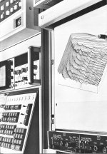
The mono-wired crossover PCB was clearly designed by hand, I remember designing PCBs with tape and stencils at the time. The lovely curvy traces are a product of that era. My first schematic design in 1982 was with a Pencil on an A0 sheet of paper. Orcad for DOS did not come into use until around 1990, when the graphics cards for the PC were good and affordable enough. I'm guessing that the main crossover components are pairs (the 100uF pairs and the HF pairs) so they could match pairs e.g. a 102uF with a 98uF but that's probably as far as it went. The positioning of the crossover inside the 104 tells me that there was zero chance of tweaking once the unit was assembled; it is too difficult to get to to take it out again and adjust it.
I can believe that the bi-wired crossover was designed using (probably home-grown) CAD. I also wrote a circuit analyser program for audio circuits at about the same time. The all-pass circuit for the second mid-range is now common but was probably groundbreaking at the time.
For me the 104/2 was an example of pre-computer design at its best. Its not quite up there with the 1969 moon landing, but it was a giant leap for audio engineering. Likewise today's LS50 Meta (connected to my PC right now) happen when you take the same audio excellence and give the engineers access to computer power. Having designed filters for UWB using nothing more than PCB copper, I can imagine that the latest 3d modelling software can help sculpt the audio filter that makes these speakers special.
KEF used computers in measurement early because I remember old white papers with impulse response and cumulative spectral decay pictures. At least a mainframe if not personal computers. Maybe they just matched crossover parts in +/- tolerance as you say and did not save filter curves. But they should have kept digital records of sorting and pairing for the reference products.
The one billion dollars question is : how is sounding the old kef 104/2 versus the brandnew Kef Meta as you have both ?
I read they measured the drivers, then matched the crossovers by selecting different inductors and cap values. They mention computer aided modeling for the crossover design of the original 104 series in the early 70's. Would be interesting to know if they kept any records for the speakers built during that era.
Attachments
- Home
- Loudspeakers
- Multi-Way
- KEF 104/2s - very odd problem