Even if a lot of caps are buyed to match them for the Left and right speaker I can't understand how it's possible to find the original values of the caps if they have moved ? (I mean this is not exactly the values marked on the body cap as the crossovers were matched at 0.5% to the original factory model !). E.G. on another speaker I have a standard 100 uF cap is exactly measured at 110 uF on each speaker... it's not by chance 🙂 ! the same for an other cap : 11 uF instead the standard 10 uF marked (the both on each speaker which is a high End Boston Acoustic speaker...)
Is there a viscosity advised for the T33 Ferrofluid ?
I can try to measure my Kef 104/2pcbs but don't see where the pcbs are ??? Have the shematic somewhere in pdf but with the standard values of the caps (not the factory model ones) if interested.
It's not possible to obtain what they were matched to in the factory. All you can do now is get a 2% toleranced set which in my opinion is good enough. It's a lot better than what they are like now. I emailed Kef to see if they had the information for each part for each serial number (they kept this information in case your speakers needed something replaced so they would keep it matched) but they destroyed all of this information years ago. Nowadays all you can do is get a tightly tolerance set of Alcaps which will come very close to the factory performance. We are talking within a percent here - splitting hairs, really, and it makes a substantial improvement which just goes to show the caps are beyond their shelf life already. To get the values just write them down, they are printed on the capacitors themselves.
I have the official disassembly instructions for this speaker from Kef. Send me a PM with your email and I will be happy to pass it along.
Sent from my iPhone using Tapatalk
Last edited:
Sorry I forgot to add. For the ferro fluid I am not sure. The original fluid is APG512a and it was made by Ferro Tec. Maybe they still have a data sheet available for it?
Sent from my iPhone using Tapatalk
Sent from my iPhone using Tapatalk
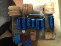
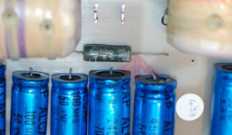
Can anyone give me a value for the large green resistor in the center of the board, next to the woofer terminals? Mine (and every other crossover I find) has the markings almost wiped off completely. I have one and it measures .8 ohms. The markings look like R08, 5 % 2 watts. R08 should be .08 ohms. I'm not sure if the resistor is bad or the markings are to faded to read properly.
Thanks!
Thanks!
Go search for a crossover schematic that matches your speakers and the answer will be revealed 😉
I've searched. No luck with a match. Apparently they had several different versions for the 104/2 speakers. My board is the SP2042. I'm hoping someone with the same crossover may know.
0.08Ω seems nonsense to me in a crossover. Even for a KEF speaker. If you measure 0.8Ω, that's probably what it should be. A defunct resistor measures infinity most of the time. And they do not really degrade that fast.

My pictures show 68Ω and that is confirmed on the following schematic.
I'd say OR 6R8. Is that Colloms, Dickason or some other book? I remember having seen this layout somewhere.
You can try asking/searching on this forum SpeakerTalk :: Index
Mcandmar, are you registered over at SpeakerTalk? They have an odd way of registering. You need to send an e-mail to the owner of the site and they send you a code. All I get back is an auto response telling me the owner gets too many e-mails and can't respond. Then, goes on to repeat the same directions to register .... send an e-mail!
I was able to do a search but can't post up a request for the schematic. The site isn't very active, they only have 1026 registered users and most of the time only about 20 visitors, none of which are registered users. Any chance I could get you to request the schematic? I'm hoping maybe some of the old timers check in from time to time.
Thanks,
Eric M.
My pictures show 68Ω and that is confirmed on the following schematic.
I did find that schematic online. I'm assuming it's a combination of the 2 boards in the 104/2. Comparing the number of caps and their values on my two boards, I'd have to say that is a different variation of the crossover I have.
Thanks
Yes, that schematic is the two boards combined. Sounds like you need to dig the crossover out of your other speaker to confirm the value at this point. You can address the tweeter protection capacitors at the same time if you haven't already.
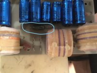
Here is a cropped picture of my crossover from the earlier posts in this thread that is clearer than the one Tim cropped. Likely from the other speaker...
Attachments
Last edited:
Hmm, both of those look like R68 which makes more sense. That would be .68 ohms. Mine measures .8 ohms. Pretty close for a 40 year old resistor, about 18% off.
Someone mentioned pulling the crossover from the other speaker. My client is out of town but I think that's the best way to go. His protection circuit caps are shot (I have to redo traces on the board I have) so we'll need to do those caps on the other board. Probably best at this point to measure the other resistor and make a decision if the original is 68, .68 or .08 ohms!
I'll report back.
Thanks for the help and cropped / enlarged pictures.
Eric M.
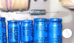
Got the second board. That resistor had better markings. R68. That's .68 ohms and both measured about .8 ohms. I'm going with .68 ohms.
I think we'll also go with the Falcon Acoustic recap kit also. It's about 8 weeks out but for the price (and the fact I won't have to stack caps to get values), we'll wait!
Thanks for the help all.
I think we'll also go with the Falcon Acoustic recap kit also. It's about 8 weeks out but for the price (and the fact I won't have to stack caps to get values), we'll wait!
Thanks for the help all.
Leaky Caps took out KEF 140/2
I just had a friend who bought them new, give me a pair of KEF 140/2s that had one speaker not working and the last time that happened, it cost him $250 to get it fixed. He knew I was into speakers, so I dove into them. Most complex speaker crossovers I've ever seen. The basic problem was the protection relay 100uF 10V caps (2) which leaked corrosive liquid on the printed circuit board which literally ate it to the point of open circuit to the Mids and Tweeters. I replaced the caps and jumpered over the traces. All sounds good now.
I just had a friend who bought them new, give me a pair of KEF 140/2s that had one speaker not working and the last time that happened, it cost him $250 to get it fixed. He knew I was into speakers, so I dove into them. Most complex speaker crossovers I've ever seen. The basic problem was the protection relay 100uF 10V caps (2) which leaked corrosive liquid on the printed circuit board which literally ate it to the point of open circuit to the Mids and Tweeters. I replaced the caps and jumpered over the traces. All sounds good now.
Hi All, I am in the middle of renovating my 1989 Kef 104/2s. I am tempted to redesign the crossover PCB if only for lower impedance tracks and better mechanical stability. My 104s have the large, single PCB crossovers but I am interested in taking a look at the dual PCB bi-wire crossover schematics for comparison. I notice that this thread showed the dual PCB crossovers. Did anyone find an original schematic?
- Home
- Loudspeakers
- Multi-Way
- KEF 104/2s - very odd problem