I'm posting this in Fullrange since most Karlson enthusiasts seem to hang out here.
The below link is a recent build of mine, a high aspect ratio Karlson for 6" drivers, which I dubbed Tall K6, TK6 for short. I initially went with a midbass, but finding it unsuitable for the enclosure, I since moved to FF125K and now dual FF125K.
https://www.diyaudio.com/community/threads/karlson-tk6-k-tube.380154/
There are some measurements in the thread, but I will post the ones I think are more relevant here. A Karlson's frequency response is often pretty horrendous, being marred by peaks and nulls. I built a K12 and Super-K8 (really a K10) in the past and took measurement, but lost most of those. The SK8 had the better response, with a dip or two and no major peaking. My present TK6 is interesting as it has all the warts present, of non-negligible magnitude to boot. I though I could pin these down to standing waves easily, but am not certain after measuring acoustically VS physically.
Here is the plan for dimensional reference. The venting was originally done mid-cab through the short horizontal shelf board, but is now four 1" holes at the top of the reflector panel. The short shelf board now reaches all the way to the back panel, but has four 1.5" holes and likely does not contribute much in the way of tuning, or could I be wrong?

Impedance with 4 vent holes open:

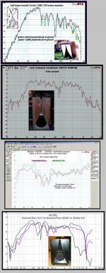
Here is the response at 50cm, cabinet elevated 25" from the floor. As all other measurements in this post, I only post the region of interest from 20Hz to 2kHz.

More telling to see what goes on in the lower octaves are near-slot measurements, where I place the microphone on the K-slot's plane a bit above the driver's axis, where the slot is 2" wide or so. I believe that the driver and vent responses are fully summed and room effects are mostly avoided, correct me if this assumption is wrong.
Here is the near-slot response with blocked vent holes, so sealed back.

Here is the response with all 4 holes open, Fb is ~67Hz.

Here is the response with all 4 holes open and the wings removed, same mic position as before.

Here is the response with wings removed and microphone at the edge of one vent hole.

The sealed response displays the three main issues; a large peak at 300Hz and large dips at 500Hz and 1200Hz.
The ~300Hz peak:
The 263Hz peak on the near-vent:
It's present as a small peak on the impedance. Peaking passed the main vent output is usually a standing wave if I understand correctly. Half-wave of 263Hz would need a ~65cm or ~26" dimension. My internal back chamber height is 20". Is it a stretch to say the slightly curvy path + bottom and top thick felt padding add to the height, making it effectively ~25" ? What else could this be?
The ~500Hz dip:
The 1200Hz dip:
This one shows up on most "normal" measurement and is fairly immutable in frequency and magnitude. I have other plots not posted here where it's the same. Even taking off the wings it's not entirely gone. This would be half-wave for ~14cm or ~5.5".
Could the typical shallow vents (board thickness) often used in Karlsons not low-pass filter enough rear-chamber interference? The XKi design's long vent seems to produce better behaved response.
I thought it would be easier to pin these on obvious culprits. The Karlson is a divisive and largely unpopular enclosure, but I like what it can do at times. If anyone cares to venture a few guesses as to my TK6-specific issues, I'd appreciate.
The below link is a recent build of mine, a high aspect ratio Karlson for 6" drivers, which I dubbed Tall K6, TK6 for short. I initially went with a midbass, but finding it unsuitable for the enclosure, I since moved to FF125K and now dual FF125K.
https://www.diyaudio.com/community/threads/karlson-tk6-k-tube.380154/
There are some measurements in the thread, but I will post the ones I think are more relevant here. A Karlson's frequency response is often pretty horrendous, being marred by peaks and nulls. I built a K12 and Super-K8 (really a K10) in the past and took measurement, but lost most of those. The SK8 had the better response, with a dip or two and no major peaking. My present TK6 is interesting as it has all the warts present, of non-negligible magnitude to boot. I though I could pin these down to standing waves easily, but am not certain after measuring acoustically VS physically.
Here is the plan for dimensional reference. The venting was originally done mid-cab through the short horizontal shelf board, but is now four 1" holes at the top of the reflector panel. The short shelf board now reaches all the way to the back panel, but has four 1.5" holes and likely does not contribute much in the way of tuning, or could I be wrong?
Impedance with 4 vent holes open:
Here is the response at 50cm, cabinet elevated 25" from the floor. As all other measurements in this post, I only post the region of interest from 20Hz to 2kHz.
More telling to see what goes on in the lower octaves are near-slot measurements, where I place the microphone on the K-slot's plane a bit above the driver's axis, where the slot is 2" wide or so. I believe that the driver and vent responses are fully summed and room effects are mostly avoided, correct me if this assumption is wrong.
Here is the near-slot response with blocked vent holes, so sealed back.
Here is the response with all 4 holes open, Fb is ~67Hz.
Here is the response with all 4 holes open and the wings removed, same mic position as before.
Here is the response with wings removed and microphone at the edge of one vent hole.
The sealed response displays the three main issues; a large peak at 300Hz and large dips at 500Hz and 1200Hz.
The ~300Hz peak:
- It's present on both sealed and vented configurations.
- It's gone with the wings removed.
- It also shows up on the near-vent trace, at high magnitude, even higher than the main vent output.
The 263Hz peak on the near-vent:
It's present as a small peak on the impedance. Peaking passed the main vent output is usually a standing wave if I understand correctly. Half-wave of 263Hz would need a ~65cm or ~26" dimension. My internal back chamber height is 20". Is it a stretch to say the slightly curvy path + bottom and top thick felt padding add to the height, making it effectively ~25" ? What else could this be?
The ~500Hz dip:
- It's present on both sealed and vented configurations. It's 515Hz for the sealed config.
- It's gone with the wings removed.
- Its depth and exact frequency changes slightly depending on how many vent holes I block, but not by a lot.
The 1200Hz dip:
This one shows up on most "normal" measurement and is fairly immutable in frequency and magnitude. I have other plots not posted here where it's the same. Even taking off the wings it's not entirely gone. This would be half-wave for ~14cm or ~5.5".
Could the typical shallow vents (board thickness) often used in Karlsons not low-pass filter enough rear-chamber interference? The XKi design's long vent seems to produce better behaved response.
I thought it would be easier to pin these on obvious culprits. The Karlson is a divisive and largely unpopular enclosure, but I like what it can do at times. If anyone cares to venture a few guesses as to my TK6-specific issues, I'd appreciate.
FWiW here's some reasonably smooth graphs. There's zero damping in the115BK and Art Welter'ss Dad's "K8" (purple trace below 0
I'll take a K12 with Kappa12A any day over my Peavey FH1 horns andK15 over reflex and any horn of its bulk.
My curved reflector K18 sounds marvelous. My SK8 sounds decent but does not make a great graph.
A "Fig.6" K15 could be made that's good. I think it would require having less front chamber depth, so it might be 36" high by22 or so wide by 15-16" deep. If K15's front shelf were removed, I suspect there will be a deeper hole.
A stub can be used to get a smooth response. GregB's Karlsonator seems to work well.
115BK's graph is ~ ground plane. IT makes an excellent substitute for a midbass horn when one has some amplifier power.
Attachments
Last edited:
Of course the bandpass nature of the Karlson does not predispose it to a smooth response above the pass-band, but I'd like to get a better grasp on how to minimize the worst of it.
I think the TK6 at least has a good BW going for it, the vented configuration sporting a -3dB passband relative to 100Hz level of 3 octaves, from 60Hz to 480Hz. Taming the 300Hz peak would make it sound better of course, even if it would cost a bit of BW at the top.
I think the TK6 at least has a good BW going for it, the vented configuration sporting a -3dB passband relative to 100Hz level of 3 octaves, from 60Hz to 480Hz. Taming the 300Hz peak would make it sound better of course, even if it would cost a bit of BW at the top.
Last edited:
Amen Brother but you can´t even mention that in a Karlson Lovers thread on penalty of tar and feathers.A Karlson's frequency response is often pretty horrendous, being marred by peaks and nulls.
Honestly can´t believe how they survived past the dark 50's.
JMFahey,
I think most Karlson enthusiasts readily recognize the problems and would not really take issue with them being pointed out. They can do good thing, especially if used as a midbass-bin. Fullrange use, as I'm trying to do here - and have done with some success in the past - does demand more optimization.
I think most Karlson enthusiasts readily recognize the problems and would not really take issue with them being pointed out. They can do good thing, especially if used as a midbass-bin. Fullrange use, as I'm trying to do here - and have done with some success in the past - does demand more optimization.
That 12LTA Karlsonator 12 displays the typical W at 200Hz. Its bandwidth before that isn't that wide, but the 12LTA might not be an ideal match either. My SK8 sort of lacked the first dip of that W, which gave it more BW, close to 3 octaves. This here TK6 has the W fairly high up in frequency. I don't recall how the K5 I built measured or if I measured it at all, but I'd have like to compare the location of the W if any.
12LTA's motor is just weak -that said, when it was mounted in a Karlson K12, sounded and behaved much better on Tom Danley's Harley track than than my Nirvana Super 10 in a bass reflex. Super10 just fluttered and farted while 12LTA in the little Karlson sounded decent.
Super10 was decent in Karlsonator 12.
I did not like Beta 10cx with EM's 2k5cx network in Karlsonator 12-just very bland. Mike Chua should have a better xover.
Kappa12 is a good driver for K12. I'd like a single vent but don't know the best placement. It would be very helpful to make a test box with removable port panel.
200 watts is a good power for Kappa 12 in K12- it really grabs on a late Rudy Rosa track ---its jaw dropping.
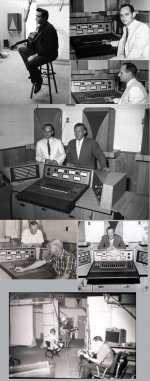
Horn maker Steve Schell knows the virtues of K15.
FWIW K15 was used in recording studios up to a point.
Super10 was decent in Karlsonator 12.
I did not like Beta 10cx with EM's 2k5cx network in Karlsonator 12-just very bland. Mike Chua should have a better xover.
Kappa12 is a good driver for K12. I'd like a single vent but don't know the best placement. It would be very helpful to make a test box with removable port panel.
200 watts is a good power for Kappa 12 in K12- it really grabs on a late Rudy Rosa track ---its jaw dropping.
Horn maker Steve Schell knows the virtues of K15.
FWIW K15 was used in recording studios up to a point.
Attachments

Last edited:
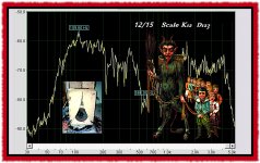
Regarding the vent and best placement, I can't say I have tried enough variations to really know. Here is a single FF125K with mid-cab venting VS dual FF125K with top-venting. SPL not relative as taken in different sessions and tweaked the volume knob in-between, normalized for the green trace's bass hump.

I earlier proposed the ~260Hz notch on the red trace is rear-wave 180deg cancellation, which should be shifted up in frequency if mid-cab vented, which might explain the steeper drop on that first dip of the W for the green trace. All in all, it might not be such a bad thing for the rear-wave null to notch a high front cavity resonance as is happening on the TK6. It really just happened and was not intended, but OTOH it's ridiculous to hope or design for irregularities to cancel each other out.
The XKi's long and high-aspect venting might have something over 'just a hole' in its low-pass filtering capabilities. I never sketched it, but had though about Ultraflex-style venting on each side of the driver slant baffle board, which would also make each of the 3 or 4 vent 'channels' of different lengths. This would further complicate the build though. The XKi's single top vent is an easier implementation and the difference would only be in the vent's location closer to the driver in my Ultraflex scheme.
From a crude Falstad simulation, it looks like the forward bend in the baffle and constriction into the upper corner of the front chamber concentrates sound at the tail of the aperture which then acts as a sort of waveguide. So basically you have a direct sound source and some fraction of that energy is channeled into the top of the front chamber to re-radiate. Then you get diffraction between the two sources, in addition to the cavity resonances.
You never mentioned the position of the vents, but if they are at the top of the front chamber then they will be unloading that corner which may be what is helping with the dips above 300Hz.
You never mentioned the position of the vents, but if they are at the top of the front chamber then they will be unloading that corner which may be what is helping with the dips above 300Hz.
Last edited:
keantoken,
Thanks for the input. I'm not familiar with Falstad and had to look it up. I'll have to see if I can simulate my cab in there for fun. I did mess about with 2D waves applets some years back to see what Karlsons do.
Thanks for the input. I'm not familiar with Falstad and had to look it up. I'll have to see if I can simulate my cab in there for fun. I did mess about with 2D waves applets some years back to see what Karlsons do.
Here is a direct link to the simulation, it's a web applet. It's 2D so it's not obvious how to model the tapered front baffle, but I extrapolate from the concentration of pressure that occurs at the top corner.
http://www.falstad.com/ripple/Rippl...8+0+9.999980322829487+1634.0638140479903+1+0
http://www.falstad.com/ripple/Rippl...8+0+9.999980322829487+1634.0638140479903+1+0
I've noticed a trend in that all Karlson response graphs are zoomed out 2x vertically so the response looks comparably flat to typical charts.
The response variation below 800Hz isn't much different than I get with room modes without being too careful about placement. So it would be funny if the variation could actually be used to compensate room modes at the listener position with enough placement attempts.
The response variation below 800Hz isn't much different than I get with room modes without being too careful about placement. So it would be funny if the variation could actually be used to compensate room modes at the listener position with enough placement attempts.
hi keantoken
what might you make of my K18 with EV18B?
Its roughly K15's bulk, has a curve reflector and size roughly 41"H x 21"w x 16" deep
With heavier 18" drivers it exhibited a mild bump outdoors @80Hz.
this is indoors withEVM18B.
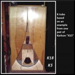
Karlson's patent 3540544 dealt with curbed reflectors and the little "X15" speaker
what might you make of my K18 with EV18B?
Its roughly K15's bulk, has a curve reflector and size roughly 41"H x 21"w x 16" deep
With heavier 18" drivers it exhibited a mild bump outdoors @80Hz.
this is indoors withEVM18B.
Karlson's patent 3540544 dealt with curbed reflectors and the little "X15" speaker
Attachments
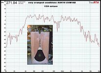
I would guess the response is better because the larger driver radiates less of the higher frequencies toward the top corner and flaps. It looks like a response I might like except for the hole at 700Hz.
so that hole is probably related to the~20" distance between the front chamber's sidewalls. (?)
keeping the front chamber and aperture, what might be the simplest change in construction to mitigate that 700Hz hole?
keeping the front chamber and aperture, what might be the simplest change in construction to mitigate that 700Hz hole?
I've already seen XRK stuff the sidewalls of the front chamber with melamine foam, seems worth a try although I don't know how thick it would need to be to be effective at 700Hz. Maybe just stuff the whole front chamber?
Of course I've never done any of this so my advice is probably garbage.
Can you post the REW file with the measurements in the first post? Looking at the time dimension may give more clues about what's going on.
Of course I've never done any of this so my advice is probably garbage.
Can you post the REW file with the measurements in the first post? Looking at the time dimension may give more clues about what's going on.
You can with the understanding that room modes/reflections are 1/2 WL while typical vented BP alignments are 1/4 WL: http://hyperphysics.phy-astr.gsu.edu/hbase/Waves/opecol.html#c1
- Home
- Loudspeakers
- Full Range
- Karlson response peaks and dips