I have a couple of questions regarding impedance related to my Infinity Kappa 9's that I think could be answered here.
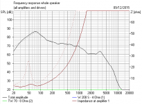
I have attached the familiar K9 impedance graph for reference.
1. In the K9 woofer xover there is a bass extension switch that when in the OFF position adds a 5ohm resistor to the xover circuit. Is the effect of this switch as straight forward as adding 5ohm to the lowest impedance of the woofer?
2. I would guess that the impedance graph was a result of measuring the K9 with the + and - speaker posts connected in single amp mode. Can anyone give me some insight as to how the Mid/High portion of the graph might change if the speaker posts were not connected such as in a bi-amped setup. I would like to know what kind of impedance resistance would be presented to an amp on the top end in a bi-amped setup.
3. And finally. Is there any reliable way to produce an impedance graph without investing in a lot of expensive test equipment or software?
I can help with measuring the impedance bit. You can plot this as long as you have either a scope or a meter that covers the audio band. Post #26
http://www.diyaudio.com/forums/mult...-loudspeaker-total-impedance.html#post4083431
http://www.diyaudio.com/forums/mult...-loudspeaker-total-impedance.html#post4083431
Is there any reliable way to produce an impedance graph without investing
in a lot of expensive test equipment or software?
Use a ~1k resistor in series with a signal generator, and measure the voltage across the speaker.
The quasi-current source produces a voltage at the speaker terminals proportional to its impedance.
You'll need an accurate AC voltmeter, or you can estimate the amplitude from the scope screen.
Last edited:
😕Post layout info for the crossover.1. In the K9 woofer xover there is a bass extension switch that when in the OFF position adds a 5ohm resistor to the xover circuit. Is the effect of this switch as straight forward as adding 5ohm to the lowest impedance of the woofer?
...
DATS for the win my friends. $99, will allow you to answer all of your questions empirically and experimentally. You could take that information into XSim and then try out any and all crossover mods. You won't be able to do speaker frequency simulation, but for $300 more you can with this combo.
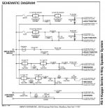
It's a monster big 5 way with an additional rear-facing tweeter. Impedance looks horrible if that graph is correct. Dipping to 1 ohm is a bit poor.😕 Post layout info for the crossover.
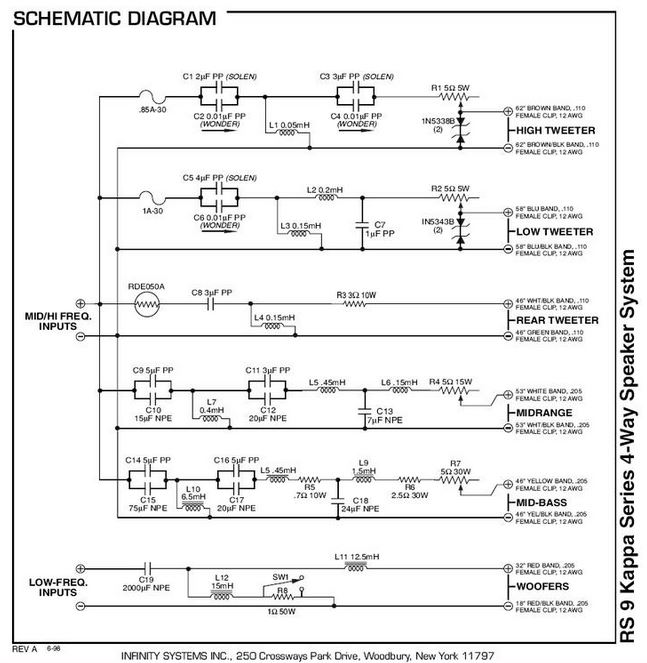
IF it's similar to the Infinity RS9 Kappa, we have this below. Hard to know where to start with that. You might set up a sim in Downloads with similar drivers and see where that goes.
Lot of work, but electrically, if the drivers are similar types, with similar 4 or 8 ohm impedance which you might measure, and you get phase right, it ought to give you a fair idea what is going on. BTW, only use an ohm multimeter on regular speakers, ribbons are fragile.
You might use some imported projekte files to get the hang of the simulator, but you'll need to set up 6 drivers from the start on a given baffle and box volumes. boxsim-db.de | Boxsim Projektdatenbank
Multi-ways can have all sorts of low impedance issues, and taking resistors in and out of circuit has surprising effects, because you're affecting filter damping.
Attachments
Last edited:
It's a monster big 5 way with an additional rear-facing tweeter. Impedance looks horrible if that graph is correct. Dipping to 1 ohm is a bit poor.
IF it's similar to the Infinity RS9 Kappa, we have this below.
Yes that's it. Thanks for uploading the Xover.
In looking at the woofer xover I see I made an error in my first post above because the switch (SW1) that I was referring to on the woofer xover engages a 1ohm resistor not a 5ohm resistor.
Maybe it would help if I explained where I am coming from and why I am asking the question. I have already completely refurbished the xovers in these speakers. I now have these speakers horizontaly bi-amped. I want to get a more accurate reading of what kind of impedance loads I am putting on the two amps in a bi-amped setup.
My woofer amp seems to be handling the bass well with the bass extension switch OFF which engages the 1ohm resistor. My concern is more with the top end amp because I have a couple of nice vintage Yamaha amps not rated to handle 1ohm loads and I don't want to risk damaging them.
My guess is that tweeter or midrange drivers dipping to 1ohm requires a lot less current than a woofer dipping to 1ohm and since it is the current demand that can damage an amp, am I safer with the lower ohm dips on the mid/high in bi-amped mode. Is this a correct assumption?
I am asking because I am under the impression that I can't rely on the impedance graph because it would change in a bi-amped configuration with the woofer xover disconnected from the mid/high xover circuit.
Last edited:
The bass section maybe has a kinder impedance with the 1 ohm taken out, but it's a bit of a horror altogether. Sort of "Whatever were they THINKING of?" design. 😕
Here's the sim of a 4 ohm load on the bass section. The dotted line is the more conventional style without the shunt altogether. But keeping the 2000uF cap. Frequency response is hardly changed.
This is the section the bass amp sees biwired. Looks like an amp frier to me! Off the top of my head, I'd reckon you could lose the series cap and the coil shunt and it'll sound exactly the same.
The top section is much more work to sim.
Attachments
Last edited:
Well, I ran some of the top section up the flagpole, but I'm not setting up a seven driver speaker here. The top section spends a lot of time around 2 ohms or less even without the two extra tweeters. 😱
FWIW, the 1 ohm resistor on the bass shunt DOES help by being switched in. The weird bass section input is a slight subsonic filter really. Acts below 50Hz by about 3dB overall.
I'd be extremely cautious with this speaker. I really don't get it. Is it designed for the 4 ohm tap of a valve amp?
Edit: I dug around a bit:
Eww.
FWIW, the 1 ohm resistor on the bass shunt DOES help by being switched in. The weird bass section input is a slight subsonic filter really. Acts below 50Hz by about 3dB overall.
I'd be extremely cautious with this speaker. I really don't get it. Is it designed for the 4 ohm tap of a valve amp?
Edit: I dug around a bit:
Many blogs and articles I've read have raised my concern though. Comments I read indicate that the Kappa 8 and 9s can be 'amp killers'. This is not a nice attribute. If I pick up a pair of the Kappa 8's - would my McIntosh get 'killed'?
Eww.
Last edited:
3. And finally. Is there any reliable way to produce an impedance graph
without investing in a lot of expensive test equipment or software?
You can measure impedance and a lot more with these for free.
ARTA Software
REW - Room EQ Wizard Features and Screenshots
Time for a review and a summary.
This is about the worst speaker design I have ever seen. It is not fit for purpose. It is full of elementary mistakes. It will damage most solid state amplifiers.

I set up a sim for electrical purposes, up to the low tweeter, and set the coil resistances to zero. Dreadful. Virtually short circuit at several points. The only thing saving the amp is the resistances of the coils themselves. Essentially most of the coils are too small, and most of the capacitors are too big. That bass section shunt is daft too.
The second image is the bi-amped filter top section on its own. Do you feel lucky? Remember there are two more tweeters to add. I wouldn't plug that in. 😀
This is about the worst speaker design I have ever seen. It is not fit for purpose. It is full of elementary mistakes. It will damage most solid state amplifiers.
I set up a sim for electrical purposes, up to the low tweeter, and set the coil resistances to zero. Dreadful. Virtually short circuit at several points. The only thing saving the amp is the resistances of the coils themselves. Essentially most of the coils are too small, and most of the capacitors are too big. That bass section shunt is daft too.
The second image is the bi-amped filter top section on its own. Do you feel lucky? Remember there are two more tweeters to add. I wouldn't plug that in. 😀
Attachments
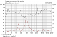
I would like to know what kind of impedance resistance would be
presented to an amp on the top end in a bi-amped setup.
Measured on the Mid-Hi input, the Impedance would be something like this.
Attachments

Buying a pair of RS Kappa 9's is like marrying a Victoria Secrets model. It has it's wonderful moments but there is a high price to pay.
Based on your reaction, you sound as though you are not familiar with the reputation of these Infinity speakers. Here in the states they are well known and frequently blogged about. (Go search for Kappa 9's in the Infinity forum on AudioKarma.org.)
Those xovers may be horrendous but commenting on the xover without listening to the speakers is like looking at that Vicoria Secrets model's spending account without seeing her. Trust me on this, these speakers are some of the best sounding vintage speakers you can find by a cost factor of over 10x. I have listened to $15,000+ speakers in high end dealer showrooms and had to suppress my laughter because they sounded worse than my Kappa 9's.
I probably have about $1,300 into these speakers counting original used purchase price and cap upgrades. And I like them so much I am willing to spend near twice that on a vintage Krell or Threshold amp rated at high current levels that won't break a sweat with these speakers.
BUT...before I go and buy a vintage class A room heater to power these speakers, is there something else you can recommend I try in the way of changing some components in the xover that would raise the impedance without impacting their great sound?
PS. Thanks for the SIM modeling you guys did in helping me. It is appreciated.
When you come onto an international forum, why assume that everybody is familiar with your niche speaker? As it goes I quickly worked out this speaker was an amp-killer. Just by looking at it.
I don't see how a speaker with a 2 ohm impedance can be considered good at all. If it was a plane it would be the Lockheed Starfighter aka "The Widowmaker". They crashed and burned. 😀
It might sound good, but that will be because of goodish efficient drivers possibly with high Qts. The crossover is a complete mess. EVERYTHING is wrong about it. There's nothing special in the topology, but the implementation is terrible. The designer has heard of the 3:1 ratio with undamped sections but gets it wrong way round in some places.
BTW, some of the origianal NP caps are there to keep the impedance higher. Replacing with film could lose you stability.
On-topic, you will do your bass amp a favour by losing the shunt coil. Probably the cap too. Bass response will slightly reduce I reckon. The rest of the circuit is a big task to repair. I think you'd have to wire the basses in series and put 6 ohms in front of every other section, or recalculate each section for higher impedance.
Last edited:
Henry - what, did you catch the VS Christmas Fashion show or something? personally, if you're gonna fantasize, I'm more of an Agent Provocateur / La Perla fan myself
As for vintage big power, how about a Marantz 500? "Back in the day" I much preferred that to the sound of the Crown DC300A,BGW 750 (remember the movie "Earthquake", in Sensurround?) Phase Linear 700, and other large power amps we had to drive the Ohm F, Dahlquist DQ10, EPI 1000 Towers, Dayton Wright XG8s, and Crown ES 224 hybrids - none of which were particularly light / easy loads
As for vintage big power, how about a Marantz 500? "Back in the day" I much preferred that to the sound of the Crown DC300A,BGW 750 (remember the movie "Earthquake", in Sensurround?) Phase Linear 700, and other large power amps we had to drive the Ohm F, Dahlquist DQ10, EPI 1000 Towers, Dayton Wright XG8s, and Crown ES 224 hybrids - none of which were particularly light / easy loads
Looks like some one could do a complete crossover re-think. I love projects like that! but only when the speakers are worth re-thinking. 🙂
Best,
Erik
Best,
Erik
Steve, I thought the early Infinity speaker line had a strong distribution in Europe. I know they did in Germany because they have a strong following there and you can find lots for sale there from this era (1980's). Here is a German website documenting the various models if you would like to read up on them.
Infinity Modelle
I even found a pair of Kappa 9 for sale near London if you want to go have a listen. 😉
Choice Hi-fi UK - High End Audio Equipment - Loudspeakers - Infinity - Kappa 9
Don't know how familiar you are with the muscle car era in the US (GTO's, Mustang, Corvette, Ford Shelby, Chevy Camero, Pontiac Firebird, Dodge Charger, etc.) that still have a strong following. Well the Kappa 9's are from the era of what I think of as the muscle cars of speakers and they need vintage muscle amps to push them. And just as you can't judge muscle cars by today's auto efficiency and safety standards, they were and still are a blast to drive.
Cheers.
Last edited:
Don't worry, boyo. We had our own amp killer, the legendary Gale GS401A. Way below 4 ohms.
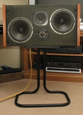
Sounded immense, it kicked your butt, but fried nearly every amp you turned the wick up with. So I know the territory. 🙂
Amusingly the published schematic has an error in it which creates an even worse dead short in the mid when you rebuild the crossover. 😱
Sounded immense, it kicked your butt, but fried nearly every amp you turned the wick up with. So I know the territory. 🙂
Amusingly the published schematic has an error in it which creates an even worse dead short in the mid when you rebuild the crossover. 😱
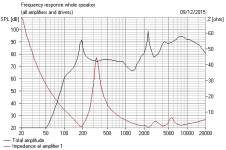
Oh I know you want to see the dodgy Gale crossover. Now what is wrong with it? TWO mistakes in the mid filter IMO. Not the parallel basses, which usually got he blame.
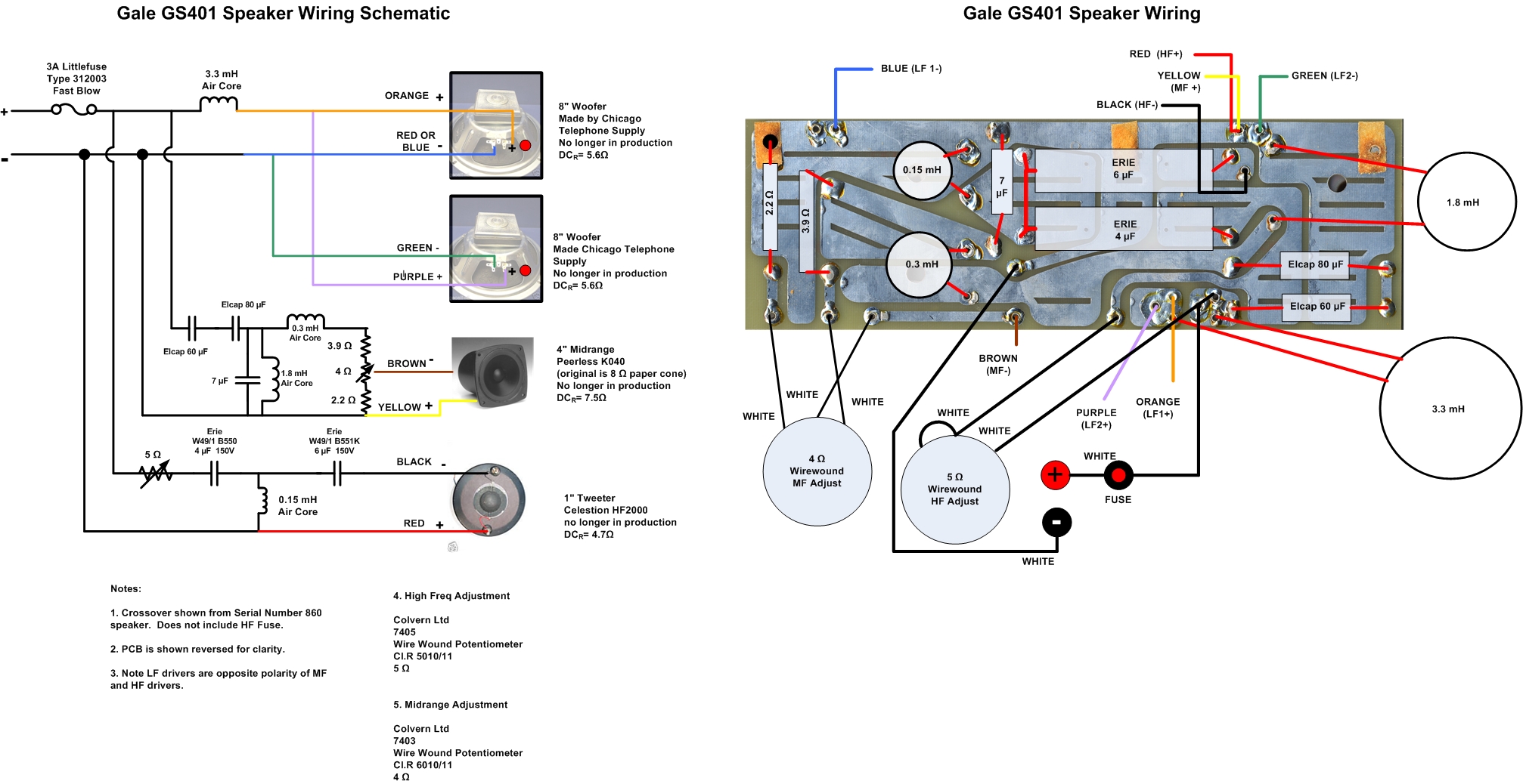
Hands up anyone? 😎
Hands up anyone? 😎
1. I noticed the 7uF cap is connected between the 0.3mH coil and the 3R9.Now what is wrong with it? TWO mistakes in the mid filter IMO.
...
2. (?) 🙂
If you want to build a new speaker with substitutes for the 8" CTS (Chicago Telephone Supply) you can use, as a starting point:
Peerless 830667 SLS-213 8" Woofer
Peerless 830667 8" Paper Cone SLS Subwoofer
https://www.madisoundspeakerstore.com/approx-8-woofers/peerless-sls-830667-8-paper-cone-woofer/
Peerless, 830667
Peerless 830667 SLS-213 8" Woofer Speaker
For mains paper cone (475 Hz and 5,000 Hz) link
Do you know a better substitute for the Peerless K040?
Monacor MSH-115HQ 😎
MONACOR INTERNATIONAL : New products
Monacor MSH-115HQ hi-fi midrange speaker from Conrad.com
Also interesting the PP (for polypropylene) driver
Peerless 830870 4" PPB Cone HDS
Peerless 830870 4" PPB Cone HDS Woofer
https://www.hifisound.de/en/Do-it-y...30870-Vifa-HDS-PPB-4-25-08-Polypropylene.html
or Peerless 830992 4" GFC Cone
Peerless 830992 4" GFC Cone HDS Woofer
Bob Gault (for CTS reference)
 Eminence is the world's #1 loudspeaker manufacturer | Eminence Speaker
- Status
- Not open for further replies.
- Home
- Loudspeakers
- Multi-Way
- Kappa 9 Impedence questions