Stands are sand filled verticals, top shelf is edge laminated ply 2" thick.
Did you check them with the stethoscope?
dave
Maybe the Satori speaker's SPL has wiggles and waggles around 120-140Hz and your ears are very sensitive in this range.
140Hz is a 96" wavelength. The cabinet panels are very small.
A medium speed sine wave sweep around 100-200Hz might uncover Wiggles and Waggles.
140Hz is a 96" wavelength. The cabinet panels are very small.
A medium speed sine wave sweep around 100-200Hz might uncover Wiggles and Waggles.
Attachments
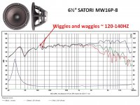
Good point obiwan, that driver plot looks a little like my in room plot! Even the 50Hz dip! Maybe it is the genetic sound of the driver! Maybe I can just cross to the woofer above that mess and fuggedaboutit.
I'll check if the bass driver/cab sounds clean through that 100-200 range. I was intending to cross around 400Hz anyway. Thanks LineSource!
I'll check if the bass driver/cab sounds clean through that 100-200 range. I was intending to cross around 400Hz anyway. Thanks LineSource!
Do you mean solid memory foam cut to size, or you mean a 2 part liquid polyurethane foam like this?
What function does the brass plate for the mid driver serve? A stiffer baffle? I always thought that a cast aluminnum driver basket was a good stiffener of the baffle near the driver's location. Not enough?
No sand box for midrange? I have read that it is ideal for midrange. No? Sand actually seems like a pretty simple method, compared to stressed panels or chemical foam injections!Maybe I won't think it's so simple building some.
The two-part foam, but higher in density (say 10 lb) - making sure it's a flexible foam (open cell or closed cell with open cell attributes) like you linked to. (..if you go to dense, even the "flexible" foam becomes far to rigid.)
Ex.
FlexFoam-iT!® Series Flexible Polyurethane Foam Product Information
Specifically iT X as seen in this video:
https://www.youtube.com/watch?v=fqj61nnvxdY
The brass plate is far more rigid than the wood, and it just seems to have the right amount of rigidity, malleability, and weight vs. other metals. The subjective result is usually an increase in clarity. (..common steel plate is a cheap alternative.) It's usually better when the driver's frame is brass as well, but that's really uncommon.
No sand for the midrange. For one thing it's a hassle to do right, for another it can "over do" things - sometimes leaving a clear, yet "shut-in" sound in the midrange and up. The larger the driver (both with regard to sd and mms) and beefier the frame, the less this happens. For instance the 12" AE driver (big Sd, big Mms, big dense frame) that Greg uses is less likely to be affected by this condition even though he uses it up into the lower treble.
Last edited:
Sorry for the pause, gents. Nothing was making sense so I had to go back to the drawing board. Thanks to Tim (twinter) for helping me eliminate the possible causes and figure out that it was too much BSC causing the wooly low mids. Wooly is relative, no other kairos owners are bothered by it, so maybe I have a sensitivity in that freq range. idk
Kairos xo has full BSC via LP coil so I used a quick and crude low shelf filter in JRiver DSP to counter the BSC baked into the passive xo and it seems to have solved the problem. This explains why other commercial speakers didn't have the same problem in my room, and why the problem improved when playing Kairos outside.
Ironically, I asked Jeff B about this wooly low mids a year ago, soon after I built the speakers. He suggested reducing the BSC to taste, but I didn't think there was "too much bass," and I didn't understand that too much BSC can change the tone. Tim helped me understand that off axis radiation and room reflections make the extra bass have different tone, and not just louder. Some other posts on diyaudio also mentioned that too much BSC can cause wooly low mids.
So before I build the adjusted passive xo, I want to do an active kairos to find the right BSC gain. The problem is JRiver doesn't have a "Baffle Step Correction" preset filter function so I have to use the "Low Shelf filter" preset. The available setting adjustment for the filter are Freq, Q, and Gain. My baffle is 9" so Freq is 500Hz. I will tune the gain by ear, probably 2-3dB. But the Q has me confused.
I understand that Q controls the slope in a standard low shelf filter, but changing the slope also changes the filter bandwidth. BSC needs a constant bandwidth with changing gain. So I think I need to use a different Q for each different gain setting, in order to maintain a constant bandwidth for the BSC. How do I figure out the Q for different gains?
btw, what is the nominal bandwidth of a baffle step anyway, in octaves?
And what is the Q for full 6dB BSC? I assume the Q of 0dB filter is 0?
Pardon if my ignorance is showing by using wrong terminology or totally confusing everything.
Thanks
Rich
Bandwidth of the BSC varies with the dimensions of the front baffle. There are numerous internet sites with equations and calculators to accurately nail down the frequency range.
Alternatively for a very simple practical concept for a common loudspeaker in the 8 to 12" width range, the baffle step frequency range can be envisioned from 200 to 1600 Hz. That is a 3 octave range (200 to 400 to 800 to 1600 Hz) with a total of 6db BCS effect. So for full baffle step, that is 2dB/octave starting at 200 Hz (0 dB) and finishing at 1600 Hz (6dB). As you adjust your total baffle step compensation for the range, the slope changes also. So for 3 dB total BSC, that is 1 dB/octave for the 3 octave range from 200 (0 dB) to 1600 Hz (3 dB).
I'm not sure if this will help, as I don't use active filters, but I saw a post by Jeff Bagby on another website:
"On the low pass filter you can use the Linkwitz Transform."
"I just switched a project I am currently working on over to all active for modeling to see how it would do. For my 9" wide baffle I "dialed in" perfect BSC using F0= 500Hz, Q0= .70, Fp= 350 Hz, and Qp= .60. The gain works out to 6.2dB. Then I needed to lower the woofer level a few dB to match things back up. I dialed this in manually by just adjusting the parameters in the LT section until I "tuned" the circuit to give me the response I wanted."
"Another option, would be to change the active low pass section to "User Entered Coefficients" and by dialing those in you can arrive at a similar transfer function shape. However, you would need to be able to translate these into an actual active circuit. If you are working with a digital filter that would be pretty easy, but it might not be with analog circuits, for those the LT may be a viable alternative. "
Last edited:
- Status
- This old topic is closed. If you want to reopen this topic, contact a moderator using the "Report Post" button.
- Home
- Loudspeakers
- Multi-Way
- Kairos cabinet