I'm working on a Hifonics Brutus BXi2607D. When I apply power and remote there is no excessive current draw as of yet... then again there is not much on.
The power transistors have 0v, 12v, 0v on the legs.
KA7500BD chip has the following readings: (All DC)
Pin 1: 6.12v (really high)
Pin 2: 2.52v
Pin 3: 4.65v (obviously causing the protection to trigger)
Pin 4: 3.95v (close to 3.5v but still a little high)
Pin 5: 1.53v (good)
Pin 6: 3.62v (not sure)
Pin 7: 0.00v (good)
Pin 8: 12.82v (good)
Pin 9: 0.00v (shut off due to protection)
Pin 10: 0.00v (shut off due to protection)
Pin 11: 12.81v (good)
Pin 12: 12.81v (good)
Pin 13: 4.9v (good)
Pin 14: 4.9v (good)
Pin 15: 4.9v (good)
Pin 16: 0.00v (good)
So from what I've been learning the Pin 1 is fed by a positive source and then some divider (assuming a resistor) drops to the proper voltage. Or something sends the required voltage to this pin. 6.12v is obviously really high causing the amp to go into protection.
What should I check for the high voltage problem on pin 1? If this is covered farther in your tutorial Perry feel free to direct me to a page. Your right, its A LOT of material. lol. I'm about half way there and loving it.
I looked for a schematic to try and follow the circuit but wasn't able to locate one.
Thanks in advance for anyones help,
Paul
Last edited:
Post the voltage on the LM293.
Pin 1: 6.72v (double checked)
Pin 2: 2.46v
Pin 3: 9.82v (double checked)
Pin 4: 0.00v
Pin 5: 1.02v (double checked)
Pin 6: 3.03v
Pin 7: .175v (double checked)
Pin 8:12.82v
Last edited:
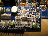
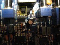
When I get back in the shop, I'll see if I have an amp with this board to see If I can point you in the right direction. If you want to try to trace it back, it's likely pin 3 that's being driven. Follow the traces (likely via resistors) to see what drives this on the main board. It may be thermistors.
I already pulled it.... :-(
I get no continuity when meter set to beep with one lead on pin 3 and the other on any of the 11 pins. Set to resistance most are high to OL except pin 11 its reading 4.7K ohms. If I use diode check (black lead on pin 3) I get .95v on pin 4 and .65v on pin 5 of the driver card, all the rest are OL.
Can't seem to see where the track goes from pin 3... maybe a 3 layer not sure...
Attachments
Last edited:
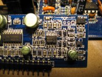
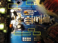
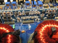
I have this??? It was from when I traced 3 pin of the power card, but I wound up at pin 11 and out to pin 8 on the audio driver card. I'll double check though... cause I was more focused on where pin 3 was going at that time.
I'll follow it around again. See if I missed something.
I'll follow it around again. See if I missed something.
Attachments
Last edited:
Yes I did. I'll go over them again.
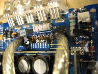
All I found on this during initial inspection was a C2690A-Y that had a broken leg from being installed on such an angle it was rubbing on the case. I removed it (tested what I thought to be O.K.), soldered on a new leg and reinstalled it. Now I'm at this point. I'll go over all the outputs again. Might even remove them all just to try to pinpoint whats going on. They are IRF640N's and IRF9640's.
When I attempt to run it my power supply (battery) rests around 12.8v. I'm using a 10amp fuse as a current limiter. With remote power applied, the green light flickers... green, then protection light comes on and green goes out, then protection turns off again, green light blinks once and protection turns on again and stays on (green light off)... all within like 1-2 seconds.
I'll check the outputs again after school.
Last edited:
- Status
- This old topic is closed. If you want to reopen this topic, contact a moderator using the "Report Post" button.
- Home
- General Interest
- Car Audio
- KA7500bd Pin 1 high??? Brutus BXi2607D