The amplifier finally got the finall "shape" after days and days of experimenting. Low feedback (28dB) realy sounds more natural and jfet input is sonicly superior to bjt at least in this design...
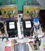
Active regulators in power supply are removed and now I got CLC filters with big iron core inductors with air gap (as you see on the picture). Whith configuration : 10mF/100mH/10mF ripple is about 5mV with the 2A bias.
The most INTERESTING thing is that removing modulation on the "Aleph ccs" I get MUCH better sound, more close, opened and detailed!
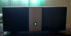
For this reason I decided to put the switch on the front chassis panel for ON/OFF modulation mode.
I wonder does Alephs sound much better without the ccs modulation ?
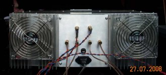
These are the pictures of setup (the chassis is on the way🙂 and finall schematic.
Cheers!
Borko.
Active regulators in power supply are removed and now I got CLC filters with big iron core inductors with air gap (as you see on the picture). Whith configuration : 10mF/100mH/10mF ripple is about 5mV with the 2A bias.
The most INTERESTING thing is that removing modulation on the "Aleph ccs" I get MUCH better sound, more close, opened and detailed!
For this reason I decided to put the switch on the front chassis panel for ON/OFF modulation mode.
I wonder does Alephs sound much better without the ccs modulation ?
These are the pictures of setup (the chassis is on the way🙂 and finall schematic.
Cheers!
Borko.
Attachments
Thanks for posting, nice circuit, good work. I enjoyed your pictures. Nice PCB layout.
Question: why use parallel current sources when P2 only monitors the voltage drop across one set (Q4) of current sense resistors? Doesn't this leave current source Q5 open-loop? What happens if you consolidate R18-21?
Anyway, some of the IRFP parts are dual (paralleled) chips contained inside of a single TO-247AC package (i.e. IRFP2907). IXYS also does this. Why use external paralleled parts instead of a single package that contains internally paralleled parts?
As long as it sounds good, it works for me 😉
ctong said:Is the bias 1A per Mosfet?
Can you hear the fan noise from the listening position?
Yes.
No.
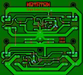
Final Version PCB
Hi,
I have updated the pcb file for this amplifier. Now I have added a switch for modulation as the author suggested and removed the resistors and capacitors around q2.
I also uploaded the updated pcb file in Sprint Layout format and Microsoft XPS file.
Please, take note that a capacitor and a resistor is required BEFORE the speaker terminals.
Yours, Darthie.
Attachments
- Status
- Not open for further replies.
- Home
- Amplifiers
- Pass Labs
- KA30se "KRYPTON" SE class A amplifier