Hey guys,
I recently built a K12G tube amp following the directions exactly. It sounds decent but it I have a couple questions.
My set up is:
-E7 Dac
-Adcom GTP-400 pre amp
-K12G 8w
-Klipsch RB61 II
1) The left two tubes glow brighter than the right tubes. Both sides are playing at the same volume and I can't really hear any differences. Is this a sign of a problem in my circuit?
2) The bass level is fine for classical music, jazz, and most rock but if I'm trying to listen to hip-hop or electronic music it falls short of my expectations (I didn't have high expectations). It almost sounds like the amp isn't touching the lower frequencies at all. Some people say that upgrading the caps will help this problem. Would you recommend this modification?
3) I'm planing to build an enclosure for the amp soon but I soldered all the parts on one side of the circuit board. I want the enclosure to show off my tubes, and I'm trying to figure out the most efficient way to do this. Can I re-solder the 9 pin connectors to the bottom of the board and attach it to the case? (essentially this would be inverting the tube).
Thanks,
Ray
Just getting the sockets out would be a pain. I remember someone on another forum with a K502 ( an amp similar to yours ) extending his sockets upwards off the pcb with leads - a lot of work! Swapping most of the components underneath has been done before IIRC. The bridge rectifier and small resistors could be left where they are. An insulating plate with cutouts for the ceramic sockets could be placed between the pcb and the metal chassis above preventing shorts. The volume pot could be removed from the pcb using extension wires ( dont forget the pot body earth ) as could the rca phono sockets.
Try swapping tubes around to see if the problem goes with them. Any mods done here on the heater tracks ?
Upgrading your output transformers will give you ( IMO ) the best bang for your buck")
The left two tubes glow brighter than the right tubes.
Try swapping tubes around to see if the problem goes with them. Any mods done here on the heater tracks ?
2) The bass level is fine for classical music, jazz, and most rock but if I'm trying to listen to hip-hop or electronic music it falls short of my expectations (I didn't have high expectations). It almost sounds like the amp isn't touching the lower frequencies at all. Some people say that upgrading the caps will help this problem. Would you recommend this modification.
Upgrading your output transformers will give you ( IMO ) the best bang for your buck
Last edited:
I switched the tubes around and the problem followed the tubes.
Does anyone have a recommendation on the Output transformer upgrade?
The Tubes are cheap, get a second set.
I have the big edcors on my K12 build, CXPP30-MS-10K, it comes out to like $150 for the pair. Trancendar also seems to have a good reputation at their price point, but I have never heard them, same with Hammond. The tubelab guys really like Edcors, the biggest you can get for your application. Whatever traffo you go for, pay attention to the frequency response. I'm not that kind of engineer, but there seems to be a correlation between size/weight and frequency response.
Also check out voltSeconds page on the k12m, all the same updates apply. S5 Electronics K-12M Tube Amp
The B+ capacitor upgrades will net more low end extension, quite a bit more. If you only do four things to that amp, get the traffo's, do the B+ caps, replace the coupling capacitors, and remove the capacitors after the volume pot. Heater inrush sharing and the snubber caps will help stabilize the heater current. I didn't go with the auricaps, I thought they made the system sound like a titanium tweeter driven to the absolute limit, I do however like the Jantzen Silver Z in the K12. But capacitor opinion is religion and philosophy around here.
I hope you enjoy.
Hi all, I'm a newbie with a K12G question I'm hoping to get some help with. This thread looked like a good place for general K12G questions, so I hope this is the right place for it.
If I want to wire in a power switch and also a fuse that would both install into a chassis, how would they be wired in to the circuit? Would it require a certain gauge of wire? (or shielding)?
Many thanks!
If I want to wire in a power switch and also a fuse that would both install into a chassis, how would they be wired in to the circuit? Would it require a certain gauge of wire? (or shielding)?
Many thanks!
I'm going to make the assumption you are using something like an IEC socket, as shown here:
Parts Express IEC Power Jack Chassis Mount
The Neutral (N pin) from the socket would just go straight to the transformer, like it does off the cable in the original kit. The Ground (G pin), would go to the chassis. The Live (L pin) would go to the fuse holder, then the switch, then the remaining wire on the transformer. For safety reasons the Live must go through the fuse and the switch, otherwise the switch could be off and you have a live wire looking to complete a circuit.
Since the original cord isn't phase aligned, one blade on the plug wider than the other, the order of hook up doesn't really matter. One wire off the cable to the transformer, the other to fuse holder, then the switch, the the transformer.
If you really want to be careful you can use a DPST, dual pole single throw, switch. Both wires from the cable go into that switch, one out goes to the transformer, the other to the fuse holder.
In my limited experience single throw switches, like a standard toggle switch, don't have pins designated as in or out. The pins are either connected or not, depending on the position of the switch. Fuse holders aren't directional either.
As far as hook up inside the chassis, I used 22 gauge silver tinned from tube depot, and that is more than enough for the short lengths of wire we use in builds. However, you MUST make sure your switch can handle the more than the 120V coming from the outlet, and the current needed by the by the circuit. An automotive toggle probably won't cut.
Happy building.
Thanks!
The toggle switch I'm looking to use is one I've seen on other folks DIY builds:
Toggle Switch with On/Off Label Plate : Toggle Switches | RadioShack.com
It says 3A at 125V. I'm not sure how much current the K12G pulls. Is there a way to know that from the K12G schematic?
For the fuse holder, I'm thinking of:
Screw-Cap Panel-Mount Fuse Holder : Fuse Holders | RadioShack.com
For the fuse itself, I should use something that will blow below the 3A toggle switch limit, but what would be best?
I haven't ordered the K12G kit yet, but plan to shortly, and researching all the extra stuff I'll need to do it right. I'm hoping to climb this learning curve quickly...
Thanks!
It says 3A at 125V. I'm not sure how much current the K12G pulls. Is there a way to know that from the K12G schematic?
For the fuse itself, I should use something that will blow below the 3A toggle switch limit, but what would be best?
Your switch and fuse holder look good.
To answer your question, yes there is a way to estimate total power draw from the schematic, but that's way beyond my ability. It can also be figured from knowing the power transformer specs.
To answer what I think you want to know, the kit comes with the appropriate fuse, just use one with the same rating for the new fuse holder. I think it's 1.5 amp, but I'd have to look to know for sure and I'm listening to that amp right now.
I would also suggest that you familiarize yourself with voltsecond's page on upgrading the K12m, but it's down at the moment...
Here is another decent write-up with most of the same mods, from that other audio forum:
S-5 Electronics K-12M Tube Amplifier Kit
The two amp's g and m, are so close the write up applies to both.
I still have most of the information in from his write up saved:
1) Omit the DC blocking caps at the input, C1&C4, they are not really necessary and I'm pretty sure they are acting as a high pass filter. You'll have to use wire or excess leads to bridge the pads on the PCB.
2) Upgrade the B+ capacitors, C5/C8/C9, to 330uf 250V. Space will be a problem here, if you decide to try this pay attention to capacitor polarity as solutions to the space issue are mounting on the other side of the board or using wire leads and chassis mounting the caps. This improves dynamic response and low frequency extension, and helps to reduce power supply ripple. This is important, PSUDII showed a pretty significant drop in ripple switching out those caps.
3) Upgrade the coupling capacitors, C2/C3/C6/C7, so something better. Voltsecond used the Auricap, I didn't like those; I went with the Jantzen Silver-Z. Lots of info here, but don't take it as gospel: Humble Homemade Hifi
4) I did this next one and I don't think it's necessary, and it goes between the HV secondaries on the power transformer and the rectifier. Voltsecond put in a split bobbin high voltage snubber, it is supposed to snub peaks and valleys as the wall voltage fluctuates. This is the really blurry picture that you may have to download and zoom in on.
5) Bridge the rectifier with an ultra-fast diode, UF4007. This also reduces power supply ripple.
6) I haven't done this, and I'm not sure if I will. But R8 and R17 can be replaced with a CCS, constant current source. The not so blurry pic.
7) Upgrade the output transformers. The stock ones aren't so great, IIRC the low end cuts out at like 80Hz. Edcor makes the CXPP30-MS-10k and I'm sure Hammond makes a comparable OPT.
So build the kit as the instructions say and get it working that way before you try to mod it. It's almost certain for your first build you will make a mistake, bridge pads, not clean up all the flux and bridge pads, or something else. Having a stock build will make it a little easier to get help.
Once it works stock up on solder wick and start making the changes you want, one at a time so you can verify everything still works and know where the problem lies if it doesn't.
If you haven't yet head over to the power supply forum and read up there, lots of good information about why a good clean power supply is necessary for a good sounding amp.
Attachments

Hi, All good but use the Edcor CXPP10-ms-10K transformers, physically smaller and work as well. I actually would (did) replace all the rectifiers with UF4005s. They are not costly and save the problem of trying to add the extra one. Jantzen Silver Z caps are fine, just a bit large physically. You might try mounting such from the bottom of the PCB. The supplied power transformer is a bit marginal IMO but OK to see if you want to upgrade further. I used an Edcor XPWR-105 on one with success. The heaters will be a bit high and if you want you can series a resistor to get the voltage lower. Something in the rang of 0.2 to 0.5 ohms at 10 watts ought be about right. (mine had the 11ms8 tubes an they are fine with 12 volts on the heaters) If you go to a bigger first power (B+) filter cap it may cause additional heating in the stock transformer. I would personally stick to about 100uf there. The CCS is a good idea, but a simpler version using a LM317 is easier to implement.
Buy the kit from who ever is cheapest.
You might want to check out some of the tube project builds on the diyaudioprojects.com site as it also covers modding the K-12.
Buy the kit from who ever is cheapest.
You might want to check out some of the tube project builds on the diyaudioprojects.com site as it also covers modding the K-12.
Thanks Bruce.
When you mention a simpler version using the LM317, can I assume you mean something like the CCS you used on your High Output Odd Block?
How would one calculate the value of the resistor on the output pins? After reading the datasheet like 5 or 6 times I couldn't figure that circuit out. I'm a software engineer not an electrical engineer.
@bmanh, take Bruce's advice over mine, this is what he does. Head over to OddWatt to see his work.
I'd like to build the high output, 45 watts RMS will drive damn near anything.
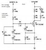
Hi, Thanks for the kind words, I have been known to dabble a bit in tube electronics . The way to calculate the resistor is divide 1.25 with a value of dc current in amperes to equal the resistor value. This is an approximate value as not all 317s are exactly the same . The resistor goes between the ground and output pins, the adjust terminal is on the ground and the input terminal goes to the cathodes. See the attached schematic of how I modded a K-12 into a what I wold consider a really nice small amp.
EDIT: you will of course have to use a power transformer suitable to the tubes heaters that you have. If you are replacing it as well then I probably would get the Russian tubes as they had what I considered the nicest sound. As mentioned in an earlier post replacing the output transformers with the CXPP10-MS-10K really makes the amp shine.
. The way to calculate the resistor is divide 1.25 with a value of dc current in amperes to equal the resistor value. This is an approximate value as not all 317s are exactly the same . The resistor goes between the ground and output pins, the adjust terminal is on the ground and the input terminal goes to the cathodes. See the attached schematic of how I modded a K-12 into a what I wold consider a really nice small amp.EDIT: you will of course have to use a power transformer suitable to the tubes heaters that you have. If you are replacing it as well then I probably would get the Russian tubes as they had what I considered the nicest sound. As mentioned in an earlier post replacing the output transformers with the CXPP10-MS-10K really makes the amp shine.
Attachments
Last edited:
@Bruce--
Your welcome, and thank you for posting how to figure that CCS. That's simple and small enough that I should have room for it in the chassis, I just may have to try that. Getting a 5 watt pot in without it touching anything will be a trick.
@bmanh--
Good luck with your first build. Even the kit sounds really good, I liked it enough that I built it point to point with higher quality parts and a beefier power transformer.
My K12G build is coming along. I've got another question that isn't necessarily K12G specific but related to what I'm trying to do with the K12G, and hoping for some advice...
PCB connections to components off the PCB such as the transformers, volume pot, and RCAs: would it be recommended to use some sort of connectors such as Molex or other so that the PCB can be easily detached from the other components upon doing later upgrades (ie. upgrading the capacitors, etc)? The types of cables are quite different - power vs. signal vs. other/speakers, so I'm not sure if different connectors would be needed in each case. I'd prefer to not solder wires directly from these components to the PCB, though, if there's another way. I've seen pics of other amps where it looks like folks have been employing connectors of various types, and it looks like a very useful way to go.
PCB connections to components off the PCB such as the transformers, volume pot, and RCAs: would it be recommended to use some sort of connectors such as Molex or other so that the PCB can be easily detached from the other components upon doing later upgrades (ie. upgrading the capacitors, etc)? The types of cables are quite different - power vs. signal vs. other/speakers, so I'm not sure if different connectors would be needed in each case. I'd prefer to not solder wires directly from these components to the PCB, though, if there's another way. I've seen pics of other amps where it looks like folks have been employing connectors of various types, and it looks like a very useful way to go.
Removing components or wires from a circuit board without damage (to either) is a "must" skill to have. A solder sucker can be used to clean up the tracks. A flux pen can be used if needed. Practicing on scrap boards first is good.
Extending the output transformer wires and fitting in-line connectors could be done but if you have the above skill then it's hardly worth the bother.
In my build ( K502 ) I needed to remove the volume pot from the pcb so that it could reach the chassis. Extension wires were used ( shielded where required ). I didn't like the quality of the binding posts so didn't use them. Didn't use the RCA sockets either. In both cases I opted to use wire extensions off the pcb out to better quality components mounted in the chassis.
I soldered most of my components to the underside of the board in order to give extra clearance to the chassis top plate. The power resistor and the cathode resistors were given good clearance off the board as they can get quite hot.
- Status
- This old topic is closed. If you want to reopen this topic, contact a moderator using the "Report Post" button.
- Home
- Amplifiers
- Tubes / Valves
- K12g Amp Question