Good day to you all,
As you can see, I am brand new here, and looking forward to contributing and get advise from the experts. 🙂
So getting right into it, I have this JVC Amp, which was working "OK", bar the 165+ mV DC I measured on the Right Hand Channel.
This is directly proportionate to the Idling Current Value, which I cannot set to the recommended 6.6 to 17.6mV.
I assume that X315 and X316 are the driver transistors, which according to the manual, should be the culprits, but the measure OK out of the circuit.
I did replace X301 through X304.
Continuing, the protection relay does not close upon power on. I have measured the coil, which was an open circuit, and duly bought a replacement unit, which still does not close.
I suspect IC401, which is a TP7317P, but I am not sure how to test these.
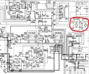
I have attached the part of this circuit for your reference, along with voltage measurements, with no input signal.
Any advice on where to go from here will be highly appreciated.
Thank you,
Jaco
As you can see, I am brand new here, and looking forward to contributing and get advise from the experts. 🙂
So getting right into it, I have this JVC Amp, which was working "OK", bar the 165+ mV DC I measured on the Right Hand Channel.
This is directly proportionate to the Idling Current Value, which I cannot set to the recommended 6.6 to 17.6mV.
I assume that X315 and X316 are the driver transistors, which according to the manual, should be the culprits, but the measure OK out of the circuit.
I did replace X301 through X304.
Continuing, the protection relay does not close upon power on. I have measured the coil, which was an open circuit, and duly bought a replacement unit, which still does not close.
I suspect IC401, which is a TP7317P, but I am not sure how to test these.
I have attached the part of this circuit for your reference, along with voltage measurements, with no input signal.
Any advice on where to go from here will be highly appreciated.
Thank you,
Jaco
Attachments
Last edited:
I did some digging on the forum and obtained a wealth of information.
Looking at the TA's datasheet, I am going to look further, and towards the lamps for the VU Meters (PL701 and PL702), which I think may have caused an issue over the past months.
I could not find the exact lamps, so I made use of 12VDC automotive interior incandescent lamps.
I think it may be causing the strange voltages on the IC.
Any thoughts?
I think you need to recheck a few fundamental things first...
It would be extremely unusual for a relay coil to be open circuit... and if this were the case then it would be a one off fault and the amp should be back to working again with a replacement fitted. I suspect more detailed testing of the relay will show it to actually be OK.
Before suspecting the IC you must measure ALL pin voltages and determine first of all whether ALL conditions for the relay to close have been met.
Check that the 'AC detect' voltage is correct. This is the -8.5 volts on C409. The cap may be bad, use an oscilloscope to determine this or else just replace it.
As long as the bulbs are not reducing the voltage on the AC winding of the transformer that supplies them then they will not be causing any problems. If in doubt just disconnect them as a test.
Thank you Mooly, I will be sure to check that as well. I must be honest, I missed that voltage completely...
My other "major" concern is also the 165mV DC on the speaker output.
My other "major" concern is also the 165mV DC on the speaker output.
The 165mv although a problem in itself may or may not be affecting the relay. This is why you must go around ALL the pins of the chip. If a voltage (such as the 165mv) seems like an issue then you you must force a correct input state to see if the ship behaves correctly.
The 165mv really needs looking at with a scope in case it is a sign of instability and oscillation rather than a more steady state voltage.
The 165mv really needs looking at with a scope in case it is a sign of instability and oscillation rather than a more steady state voltage.
Hey Mooly,
It turns out that D404 was the culprit. It was physically broken in half, so no voltage was getting through.
This is a zener diode, 1S2473, which is not available locally in South Africa.
I am looking at BZX83C36V as a replacement. Any thoughts on this?
And thanks again for highlighting another part of the circuit for me to look at.
D404, now that isn't drawn as a Zener and tbh I can't see how a Zener could work... it would conduct each way around (0.6 v drop in one direction and whatever the Zener voltage was in the other) and that would put effectively AC across that little cap (you must change that cap in any case).
I would have though a 1N4002 or similar would be fine, any standard rectifier really.
I would have though a 1N4002 or similar would be fine, any standard rectifier really.
You are quite correct and I see that some sites on Google refer to it as a Schottky Diode.
But it makes sense that "any" general purpose rectifier diode will also do the job.
Will replace it today and supply feedback.
But it makes sense that "any" general purpose rectifier diode will also do the job.
Will replace it today and supply feedback.
I replaced D404 and C409.
I also found a loose coil wire when I opened the relay cover, soldered that and voila, all in order and the circuit operates as normal.
Thank you for the assistance once again.
Now, only the matter of the 165mV on the right channel output; but in saying this, if the protection circuit thought that this was an issue, surely it would have released the relay?
Any thoughts?
Good to hear that bit of the circuit is working OK.
Most offset circuits need 1 to 2 volts to trip. Offsets of -/+100mv were considered acceptable many years ago... 165mv... not damaging but I would want to know why it was like that. It is high enough to warrant investigation imo.
Does the offset trimmer do anything?
You mentioned in post #1 that you swapped some transistors. The balance of the input stage is critical to low offset... that may be your issue. The transistors should be closely pair matched for minimum offset.
Different transistors can sometimes show up as causing instability which in turn can show as an increased offset. A scope check will rule that out in seconds.
Correct, I replaced X301 through X304 as well as the 2 pots R311 and R312 (reason being that when I measured R312 out of the circuit, it was all over the place).
Adjusting the pots, specifically for the right channel, does not bring it down to 0V; it hovers around 160mV.
Strange thing is, all input voltages to IC301 and IC302 are on spec, but on pins 3 and 8 of IC302, I pick up the 165mV DC.
This is where I am stuck...
Adjusting the pots, specifically for the right channel, does not bring it down to 0V; it hovers around 160mV.
Strange thing is, all input voltages to IC301 and IC302 are on spec, but on pins 3 and 8 of IC302, I pick up the 165mV DC.
This is where I am stuck...
Last edited:
As an experiment try swapping X301 with X303 and see if the offset changes.
Did you replace X307 and X309?
Did you replace X307 and X309?
- Home
- Amplifiers
- Solid State
- JVC JA-S22 Amplifier protection circuit