Finished Board New TPA3123 2 1 Digital Power Amplifier Board Subwoofer Output | eBay

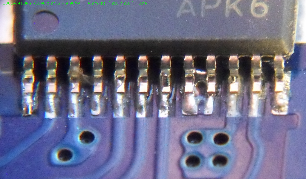
There is a solder bridge between pins 8 and 9 on the primary ICs. It worried me at glance but it's a clean bridge that doesn't look accidental, and it is the same on both chips. The thing is, if you zoom in as close as possible on that photo from ebay for the original board there is no such bridge. I suppose I'll send the question along to the seller, but I thought I'd get some opinion here too.
Nothing to worry about?
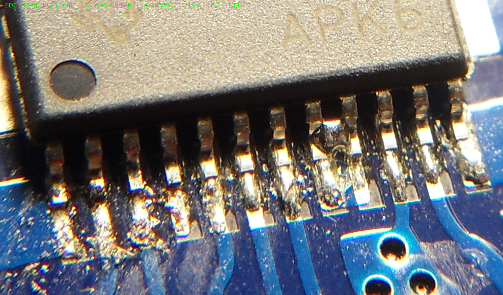
Not the most beautiful solder joins. Hand assembled I guess. But that right chip. Ugh. Uncleaned flux and shitty joints. It's almost as if two different people soldered each chip. I'll have to clean up that flux and brush the debris away to be 100 percent certain there are no real problems with this one.
But the board is guaranteed to work, supposed to be pretested, ya ya ya. We'll see. I haven't run it up yet.
Left TPA3123D2
Right TPA3123D2
By the way, I just read a post here where a member said he'd love to own a "high res" camera to get close-up shots of electronics. Any modern compact camera above 10mp is "high res" enough. I think he meant a camera with swappable lenses capable of real macro shots when you need them.
I've got a 90 dollar Samsung. I got a tip online to use the front lens from a cheap pair of miniature binoculars (two dollars at Goodwill). Just remove the lens and throw the rest away (keep the other lens for spare of course). When you need closeups just hold the lens against the compact's lens on auto focus. It really works surprisingly well. If you want to get fancy you can make some quick and dirty adapter to keep the lens in place. But I just hold it lightly against the front lens carriage, let the auto focus do its magic, and shoot.
There is a solder bridge between pins 8 and 9 on the primary ICs. It worried me at glance but it's a clean bridge that doesn't look accidental, and it is the same on both chips. The thing is, if you zoom in as close as possible on that photo from ebay for the original board there is no such bridge. I suppose I'll send the question along to the seller, but I thought I'd get some opinion here too.
Nothing to worry about?
Not the most beautiful solder joins. Hand assembled I guess. But that right chip. Ugh. Uncleaned flux and shitty joints. It's almost as if two different people soldered each chip. I'll have to clean up that flux and brush the debris away to be 100 percent certain there are no real problems with this one.
But the board is guaranteed to work, supposed to be pretested, ya ya ya. We'll see. I haven't run it up yet.
Left TPA3123D2
Right TPA3123D2
By the way, I just read a post here where a member said he'd love to own a "high res" camera to get close-up shots of electronics. Any modern compact camera above 10mp is "high res" enough. I think he meant a camera with swappable lenses capable of real macro shots when you need them.
I've got a 90 dollar Samsung. I got a tip online to use the front lens from a cheap pair of miniature binoculars (two dollars at Goodwill). Just remove the lens and throw the rest away (keep the other lens for spare of course). When you need closeups just hold the lens against the compact's lens on auto focus. It really works surprisingly well. If you want to get fancy you can make some quick and dirty adapter to keep the lens in place. But I just hold it lightly against the front lens carriage, let the auto focus do its magic, and shoot.
Last edited:
They are both ground pins so it's OK.
You can see by the solder mask that both pads are connected.
You can see by the solder mask that both pads are connected.
I'd check the pinout of that chip to see just what's getting bridged. That's an unusual ECO, if those pins should have had a connecting trace.
And that solder job on the Right TPA3123D2 looks like hammered Jello. I'd dump some flux on there and give that some neatness.
And that solder job on the Right TPA3123D2 looks like hammered Jello. I'd dump some flux on there and give that some neatness.
I'd noted that on some pins on the other side as well. But why the need to drop a bridge on the pins when the board trace already joins them? But you're correct. Either way it does not matter. But that right one might need a little rework just to be on the safe side.You can see by the solder mask that both pads are connected.
Hammered Jello. That's good. It's a collectible. Sure I'll use it at some point soon!
Last edited:
If they are connected, the heat during soldering will transfer to the other pin, and take solder with it. Since they are connected anyway, there's no reason to flag it for rework.But it begs the question as to why the need to drop a bridge on the pins when the board trace already joins them?
My pleasure. I sanitized it to keep the forum family-friendly!😀Hammered Jello. That's good. It's a collectible. Sure I'll use it at some point soon!
Thanks, sounds good. Tomorrow I'll test. It's going to be a fun little project. I'll log it here if I have any success.
I'm reworking better drivers and amp into a little Sony AM/FM/CD clone of the Bose Wave radio.

It's got two little 3.5 mains and a 4.0 "sub" woofer in the back loaded into that discrete slot that exits out the front. I've got two Vifa 3.5s and a Dayton neo mag 4.0 that I'm wresting into the chassis along with this amp.
The amp is really tiny enough to be the least of the concerns. The new drivers are all slightly larger than the OEMs and will need a little shoehorning here and there.
I'll use this in the kitchen along with a hidden 10" subwoofer so that guests will look at it and wonder "holy $#!t, where is that coming from.... that little clock radio?"
As long as I've got your attention here I'll ask some advice on the second step.....
This is where I anticipate tapping into the Sony. Right off of the main volume control for signal level output to the chip amplifier....
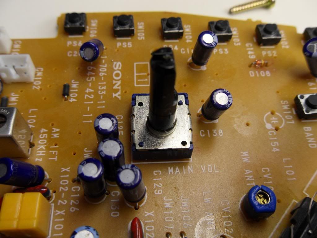
These are the pins on the opposite side....
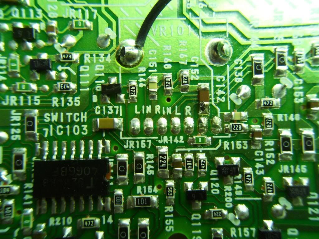
LIN RIN in L/R
Little help here on precisely how I tap into these to connect to the 2.1 amp module? There are a few alternatives. I can tap directly in and use the existing volume pot to control the amp...... and leave the three pots from the amp accessible from the rear for adjustment. Or I can replace the main volume pot on this board with the one one from the new amp and take one control out of the loop.
What would you do?
I'm reworking better drivers and amp into a little Sony AM/FM/CD clone of the Bose Wave radio.
It's got two little 3.5 mains and a 4.0 "sub" woofer in the back loaded into that discrete slot that exits out the front. I've got two Vifa 3.5s and a Dayton neo mag 4.0 that I'm wresting into the chassis along with this amp.
The amp is really tiny enough to be the least of the concerns. The new drivers are all slightly larger than the OEMs and will need a little shoehorning here and there.
I'll use this in the kitchen along with a hidden 10" subwoofer so that guests will look at it and wonder "holy $#!t, where is that coming from.... that little clock radio?"
As long as I've got your attention here I'll ask some advice on the second step.....
This is where I anticipate tapping into the Sony. Right off of the main volume control for signal level output to the chip amplifier....
These are the pins on the opposite side....
LIN RIN in L/R
Little help here on precisely how I tap into these to connect to the 2.1 amp module? There are a few alternatives. I can tap directly in and use the existing volume pot to control the amp...... and leave the three pots from the amp accessible from the rear for adjustment. Or I can replace the main volume pot on this board with the one one from the new amp and take one control out of the loop.
What would you do?
Last edited:
- Status
- Not open for further replies.