Hi,
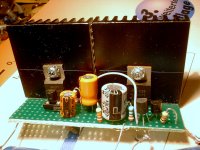
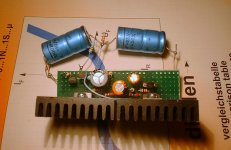
Here is a little exercise in style: to design a complete class B amplifier using almost exclusively voltage regulator chips (only one discrete transistor is used at the input).
The results are quite surprising: the simulation shows it works nicely, and even more surprising, the reality agrees very well with the sim.
At 1KHz, the distortion is quite low (the actual measured figure is ~0.05%, but it isn't bad anyway).
The quiescent current is very stable and predictable, and there is no risk of thermal runaway, thanks to the tight regulation.
Moreover, the circuit is inherently immune to short-circuits and over heating, thanks to the internal protections of the chips.
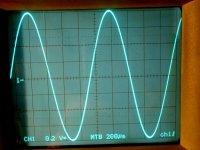
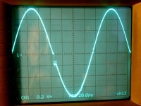
There is one snag however: the chips are slow, and if a certain slew rate is exceeded, the waveform breaks down: this is visible on the 7KHz oscilloscope screenshot (the same happens in sim, but at a higher frequency).
The prototype used a LM336 instead of the LT1009.
Have fun!
Here is a little exercise in style: to design a complete class B amplifier using almost exclusively voltage regulator chips (only one discrete transistor is used at the input).
The results are quite surprising: the simulation shows it works nicely, and even more surprising, the reality agrees very well with the sim.
At 1KHz, the distortion is quite low (the actual measured figure is ~0.05%, but it isn't bad anyway).
The quiescent current is very stable and predictable, and there is no risk of thermal runaway, thanks to the tight regulation.
Moreover, the circuit is inherently immune to short-circuits and over heating, thanks to the internal protections of the chips.
There is one snag however: the chips are slow, and if a certain slew rate is exceeded, the waveform breaks down: this is visible on the 7KHz oscilloscope screenshot (the same happens in sim, but at a higher frequency).
The prototype used a LM336 instead of the LT1009.
Have fun!
Attachments
Always wondered how well they would work! We talked about it at lunch back in the mid-1980's, but that's as far as it got.
How interesting😀
I'm wondering if it's possible to design a "quasi-complimentary" version? It could be, right? I'm no expert, but it's commonly seen that the positive Vregs are slightly better than negative ones.
So, how about one with 2 LM338, maybe approaching 100W per channel😀 At least at its peak.
I'm wondering if it's possible to design a "quasi-complimentary" version? It could be, right? I'm no expert, but it's commonly seen that the positive Vregs are slightly better than negative ones.
So, how about one with 2 LM338, maybe approaching 100W per channel😀 At least at its peak.
With a quasi-complementary, you'd still need a low power negative regulator.How interesting😀
I'm wondering if it's possible to design a "quasi-complimentary" version? It could be, right? I'm no expert, but it's commonly seen that the positive Vregs are slightly better than negative ones.
But these devices already have a huge transconductance compared to any discrete, and cascading them looks a like a sure method to get uncontrollable oscillations.
I have considered alternatives: the circlotron is one of them, but there is a difficulty: compared to a MOS or a BJT, voltage regulators are depletion devices: they need a negative bias on their control electrode (=~base) wrt. the reference electrode, the output (=~emitter).
This means that for class B operation, you'd need a small negative auxiliary supply of ~1V.
Not very practical.
Class A would be possible, a bit like a tube: the cathode resistor would provide the negative bias.
Note that by operating at a higher quiescent current, it is possible to remove the artifacts seen on the 7KHz sinewave.
Normally, since I have tin ears, I don't perform this kind of tests. I don't want to make a fool of myself, and I prefer to let others do it.nice, how does it sound🙂
I did feed some music however, and it sounded normal: there was no gross deficiency, and without knowing I certainly wouldn't be able to distinguish between this amplifier and a "normal" one.
This probably means the content of the program remained below the critical slew rate, because if it had been exceeded, even I would have detected it.
- Status
- Not open for further replies.