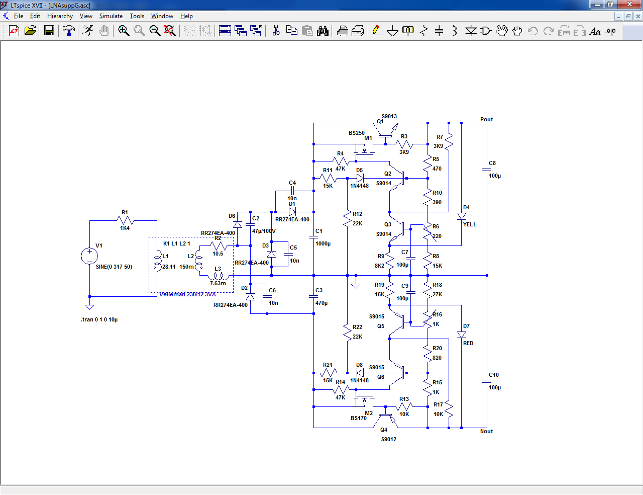
It is easy to see that M1 forms the "input" of a complementary
pair / Sziklay pair, used in a series regulator, no current source.
pair / Sziklay pair, used in a series regulator, no current source.
I have not seen yet, the name Sziklay about a BJT and FET.
Some auto proclaimed expert wording, I presume.
What are the salient features of such a pair of transistors ?
Some auto proclaimed expert wording, I presume.
What are the salient features of such a pair of transistors ?
You could call it a "hybrid Sziklai"or "hybrid CFP", but that's just nitpicking.
What matters are the function and properties:
Compared to a hybrid darlington ( or a "MOSlington"), it has a saturation voltage of ~1Vbe instead of Vbe+Vth, thus an appreciable gain of efficiency.
Compared to a regular, BJT CFP it has a ~zero input current, thus an ~infinite input resistance, allowing a high, unhindered voltage gain.
Ultimately, yes, but something needs to pull up the the gate of the PMOS, and it has to be either a resistor or a CCS.
On paper, a CCS looks better, but 47K is already extremely large taking into account the fact that Q2 is a cascode, Q3 being the actual gain stage.
Q3 is biased at a relatively large Ic, Ie, thanks to R7, and this sets its effective transconductance.
The gain is thus gm(Q3)*47K, which is substantial, and the circuit needs to be compensated, which is achieved mainly thanks to the Miller capacitance of the MOS.
Increasing the gain with a CCS would improve the VLF/DC gain, but not the rest of the audio band.
It would also increase the component count.
One might argue that a transistor could be better spent in a CCS rather than a cascode, and both are probably broadly equivalent, but the Early effect of Q3 operating at a highish current would degrade the PSRR, which is not the case here (and an explicit compensation would be required).
If you break the <12 components requirement, improvements are of course possible, but it is no longer within the scope of this thread....
*all components references are relative to the positive side of this schematic:
Yes, and it doesn't qualify anymore as a "superreg" (in this context, a superreg is just something significantly better than a cap-fitted 317)
NTR5105P, BSS84 are examples.
For dual polarities, you can also find complementary transistors in a single package.
It also depends on your preferences: SMD or TTH, your favorite supplier, etc
If you state your exact requirements: current, voltage, starting method, I can adapt the schematic for you (in sim, I am not going to test it physically)
Hi, i need positive/negative smd regulator which will output +/-7V with as low drop out as possible, maximum current load is <200ma, starting method should be simple.
Woah, thanks.Ultimately, yes, but something needs to pull up the the gate of the PMOS, and it has to be either a resistor or a CCS.
On paper, a CCS looks better, but 47K is already extremely large taking into account the fact that Q2 is a cascode, Q3 being the actual gain stage.
Q3 is biased at a relatively large Ic, Ie, thanks to R7, and this sets its effective transconductance.
The gain is thus gm(Q3)*47K, which is substantial, and the circuit needs to be compensated, which is achieved mainly thanks to the Miller capacitance of the MOS.
Increasing the gain with a CCS would improve the VLF/DC gain, but not the rest of the audio band.
It would also increase the component count.
One might argue that a transistor could be better spent in a CCS rather than a cascode, and both are probably broadly equivalent, but the Early effect of Q3 operating at a highish current would degrade the PSRR, which is not the case here (and an explicit compensation would be required).
If you break the <12 components requirement, improvements are of course possible, but it is no longer within the scope of this thread....
*all components references are relative to the positive side of this schematic:
This is the answers to questions I did not dare to ask, and with very interesting comments.
The initial version, without additional caps, was <12, and it already worked and qualified as a superreg:Since you are already at more than 12 : bootstrap for R4, two more components ..
The later version, also without caps but with the split cascode resistors was exactly at 12.
Regarding a bootstrapped R4 (R7 in the schematic above), I do not see where you would tie the other end of the cap.
OK, I will study your case and come back with a propositionHi, i need positive/negative smd regulator which will output +/-7V with as low drop out as possible, maximum current load is <200ma, starting method should be simple.
You are welcome, and remember that there are no silly questionsWoah, thanks.
This is the answers to questions I did not dare to ask, and with very interesting comments.

Here is a first example, based on ordinary SMD components:Hi, i need positive/negative smd regulator which will output +/-7V with as low drop out as possible, maximum current load is <200ma, starting method should be simple.
I uses a BCP54 as a pass transistor, it is the same as your BCP56 except it has a lower voltage.
R1 R10 and D3 form a permanent startup circuit.
I have included the cheat capacitors; they could be reduced or omitted if the full performance is not required.
For a 7V output, C1 needs a 6V3 rating; for C4, 3V is enough.
This sim shows the circuit operating ~at its minimal dropout voltage, a little under 1V.
The output is a shade over 7.1V, and the input is 8.1V.
In these conditions, the output impedance is ~700µΩ.
The output voltage can be trimmed by inserting a trimmer at the junction of R5 and R6.
The reference LED is a blue or white type.
With the BCP's as pass transitors, the max input voltage for 200mA output is 12V.
Only the positive side is shown, but the negative side is identical, except the polarity of transistors is the complementary type (BCP51 for the ballast, etc), and the diodes and Ecaps are reversed.
I include the .asc, if you want to play and experiment
Attachments


Regulation and step response - are these correlated to output impedance (etc?) or can they vary?
//
//
Under small signal conditions, step response (current step) and output impedance are 100% correlated: the time domain response can be mathematically transformed into the frequency domain and vice-versa.
Small signal would be for example a step having <10% of the standing current.
If you use a large step, 10% to 90% for example, the operating conditions change significantly and the response is no more linear, meaning it has to be tested in the time-domain, or with a transient analysis in sim.
Regulation is not covered, because the frequency is 0Hz, and it has to be evaluated with DC conditions
Here is a first example, based on ordinary SMD components:
I uses a BCP54 as a pass transistor, it is the same as your BCP56 except it has a lower voltage.
R1 R10 and D3 form a permanent startup circuit.
I have included the cheat capacitors; they could be reduced or omitted if the full performance is not required.
For a 7V output, C1 needs a 6V3 rating; for C4, 3V is enough.
This sim shows the circuit operating ~at its minimal dropout voltage, a little under 1V.
The output is a shade over 7.1V, and the input is 8.1V.
In these conditions, the output impedance is ~700µΩ.
The output voltage can be trimmed by inserting a trimmer at the junction of R5 and R6.
The reference LED is a blue or white type.
With the BCP's as pass transitors, the max input voltage for 200mA output is 12V.
Only the positive side is shown, but the negative side is identical, except the polarity of transistors is the complementary type (BCP51 for the ballast, etc), and the diodes and Ecaps are reversed.
I include the .asc, if you want to play and experiment
Thanks, is the led important here, or just general led will work?
Practically any small blue or white LED will work similarly; there will be slight differences in the output voltage, but if the value needs to be accurate, you can always add a small trimmer, or better: select the value of R6 if you have access to E192 series resistors, and if you haven't, use a slighly larger for R6, 3.3K for example, and adjust the voltage by soldering a suitable, larger value resistor in parallel (trimmer aren't very good, they add noise and instability; fixed resistors are much better).
If the LED is unbypassed, they will have some differences; the tendency from Gerhard's measurements, the brighter = the noisier.
The one I used in my test prototype is a cheap, generic Chinese type and has 0.9µV over the audio range.
With a parallel cap, differences vanish, of course
If the LED is unbypassed, they will have some differences; the tendency from Gerhard's measurements, the brighter = the noisier.
The one I used in my test prototype is a cheap, generic Chinese type and has 0.9µV over the audio range.
With a parallel cap, differences vanish, of course
- Home
- Amplifiers
- Power Supplies
- Just for fun: a superreg with <12 discretes??! ?! ?