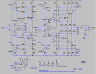
I employed a few tricks such as improved wilson current mirrors, dual BC847/857 packages and CFP output with parallel BJT drivers so I can bias the output stage fully into Class A even into 16R. I also used the DC servo from hpasternack's A4. So far, I'm getting 0.0007% THD with 2Vrms input, ~7.8Vrms output into 16R at 20kHz and I'm quite happy with that result, but I was wondering if there was any way I'm missing that I could optimize this circuit further.
I'll post further measurements later, currently not home as I post this!
I'll post further measurements later, currently not home as I post this!
Attachments
Last edited:
I have decided to call this amplifier the Mirza! I slightly lowered the gain to 4.64 and got rid of the parallel transistors for a single TO220 per side. Quiescent current is ~473mA per device.

Power and Vrms measurements, 2Vrms in at 1kHz, 16R, 32R, 64R, 150R, and 600R loads.

Gain/phase margin.

Loop gain.

Power and Vrms measurements, 2Vrms in at 1kHz, 16R, 32R, 64R, 150R, and 600R loads.
Gain/phase margin.
Loop gain.
Last edited:

LGS is loop gain single, the parameter used by the Tian probe LGS to measure loop gain and phase margin.
Edit: used this video:
Edit: used this video:
It looks a bit complicated at first.
But it is really well designed using CFA.
I bet it can sound nice ... no doubt it works well.
I think you can improve it further.
But it is really well designed using CFA.
I bet it can sound nice ... no doubt it works well.
I think you can improve it further.
This is very similar to my preamplifier, at list the gain part. https://www.diyaudio.com/community/...re-phone-amp-with-very-low-distortion.296545/
I hope that your inspiration is comming from that preamplifier.😉
I hope that your inspiration is comming from that preamplifier.😉
Yeah, the baxandalls (I think that's what they're called) specifically were inspired by your design 😛
Can be expected that such a custom made layout will be better than a chip amp which was modified to current feedback like Rod Elliot lm3875 or Adasons Lm3886 converted to current feedback?
Maybe? As mentioned previously this is my first 'serious' amplifier that I designed from the ground up, but I'll do my best to lay it out in an optimal manner! I know I need to minimize current loops and use a good grounding topology at least.
As for the changes I made, I increased R2/R3 to 330R, which has changed the current to 1.25mA and the power through Q3/Q4 to a far more reasonable 20.64mW. I also decreased Q25/Q26's bias to 234mA as I decided I didn't need the output stage biased into class A into a 16R load. I also changed the values in the gain cell C1 || R17 which has had a corresponding effect on the loop gain and phase margin.


Could It be used as a headphone amp? If so I wonder if a 4 gang? volume pot could be used and a circuit could be made so that the headphone socket will switch the amp to a lower gain and disconnect the speakers as soon as the headphone is inserted? Sorry for this diversion. I just noticed it could drive high impedance, and it would be a cool feature.
Cheers!
Cheers!
This was designed as a headphone amp first and foremost! That's why I'm testing at 16 all the way to 600R.
For my next set of changes, I drew inspiration from the Marantz HDAM SA-3 cascoded diamond stage in my IPS, greatly increased the current output into the Baxandalls and utilized transitional miller compensation across them.


- Home
- Amplifiers
- Headphone Systems
- Just another current feedback amplifier